
Device for protection against transitory overvoltages

a technology for overvoltage protection and components, applied in emergency protection arrangements for limiting excess voltage/current, emergency protection arrangements for automatic disconnection, electrical equipment, etc., can solve problems such as disabling protection devices, catching fire, melting of thermofusible elements and thermal disconnection, etc., to achieve better sensitivity to disconnection

Active Publication Date: 2017-11-16
CITEL
View PDF5 Cites 0 Cited by
  • Summary
  • Abstract
  • Description
  • Claims
  • Application Information

AI Technical Summary

Benefits of technology

The invention is a device that protects electrical equipment from transitory overvoltages to ensure safe and reliable disconnection at the end of life. It includes a thermofusible soldering discharge tube and a varistor connected to a housing with two connection terminals. The device prevents any electric arc between the varistor and discharge tube and is designed to be compact. The technical effects of the invention include better sensitivity to disconnection, fire protection, and compact design.

Problems solved by technology

On the other hand, for a varistor the end of life may involve an explosion for pulsed phenomena or a strong decrease in its internal resistance (tending to a short circuit), which often may result in its catching fire.
The mains voltage is then entirely placed on the varistor, which heats up, resulting in the melting of the thermofusible element and thermal disconnection, i.e., the disabling of the protection device.
However, it is hard to make certain of the reliability of the disconnection produced by the melting of the thermofusible element.

Method used


Image

  • Device for protection against transitory overvoltages
  • Device for protection against transitory overvoltages
  • Device for protection against transitory overvoltages

Examples


Embodiment Construction

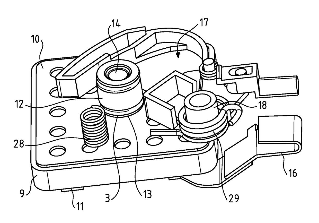
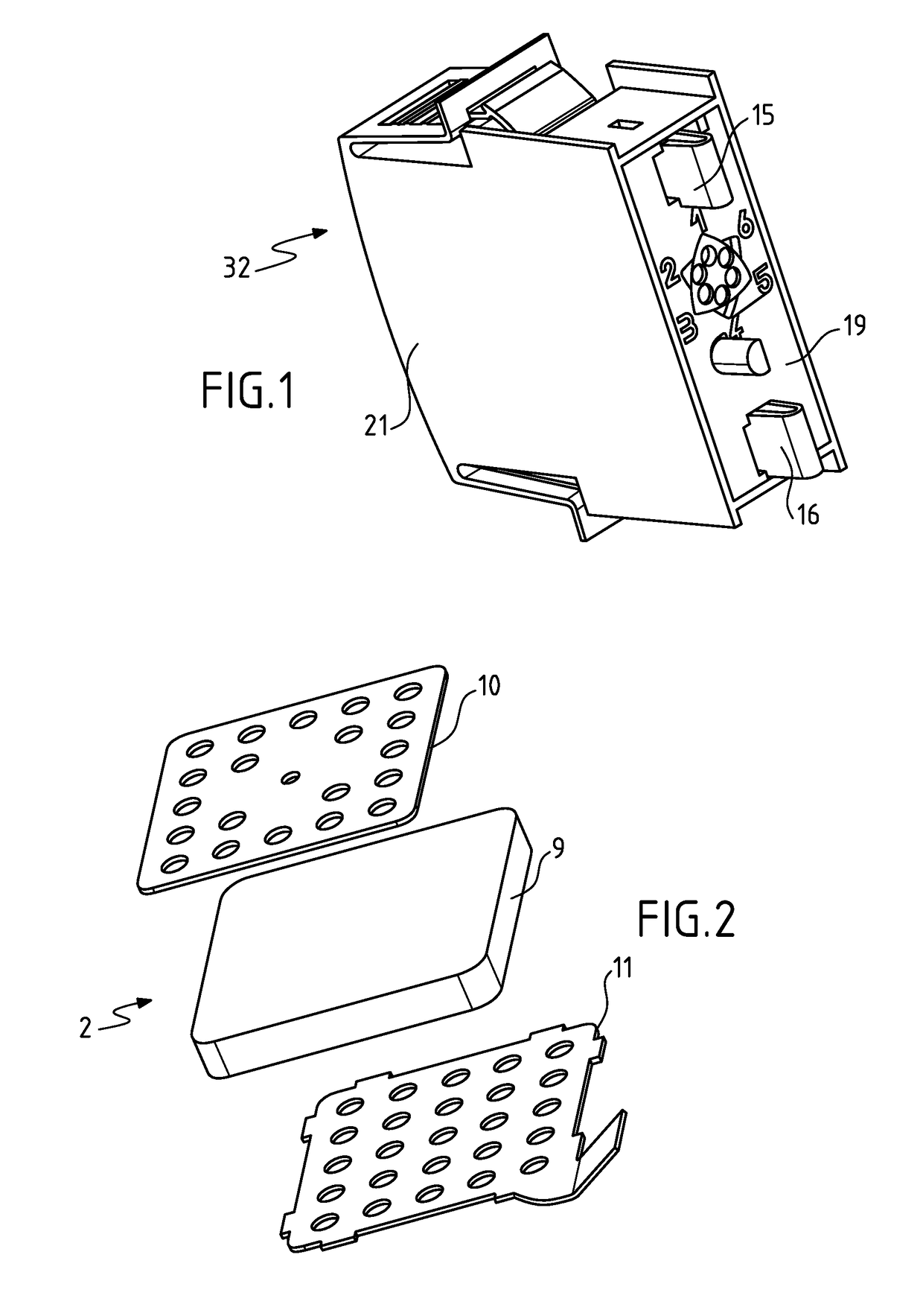
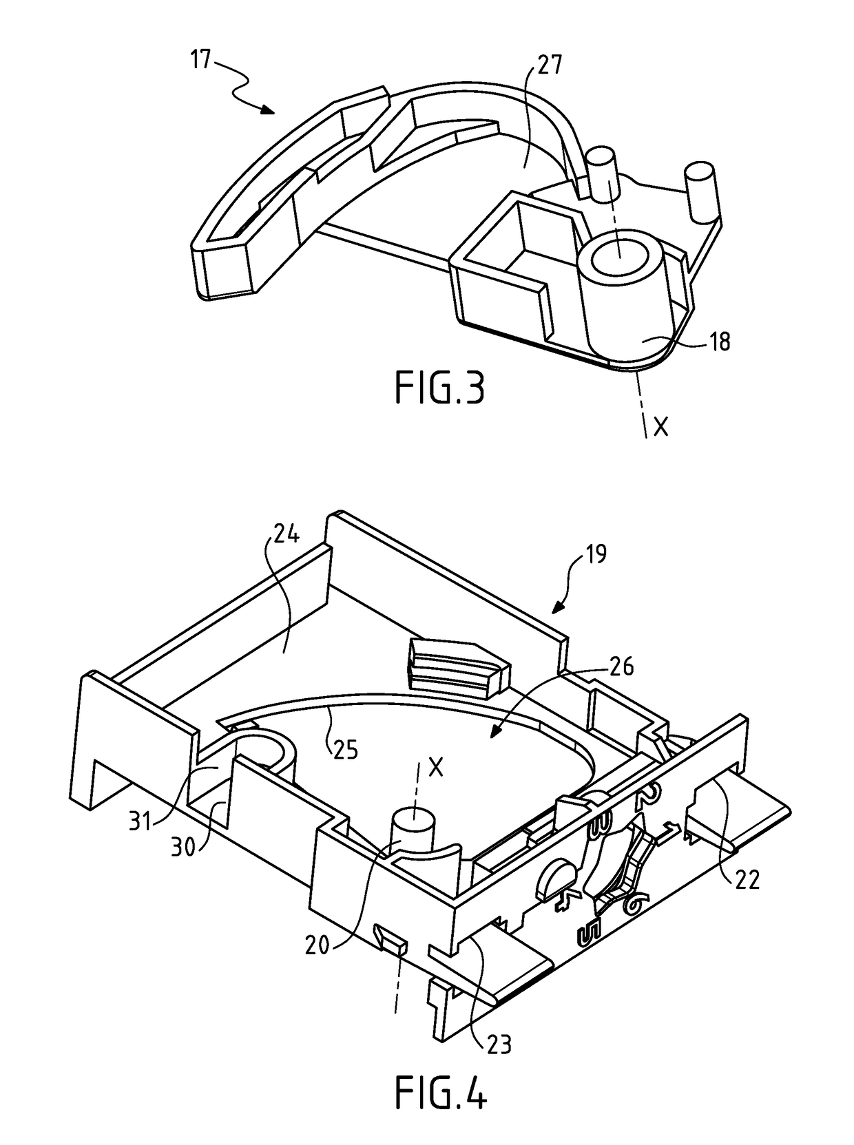
[0063]A device 1 designed to protect electrical equipment against overvoltages shall now be presented with reference to the figures.

[0064]The equivalent electrical diagram of a protection device 1 according to the invention shall be described in relation to FIG. 11. The device 1 comprises a discharge tube 4, a varistor 2 and a thermofusible soldering 3 mounted in series between two electrical lines 5 and 6 of the circuit or electrical equipment being protected. The electrical lines 5 and 6 may be any conductor serving to bring electric power under a low or medium voltage to electrical equipment. The thermofusible soldering 3 is connected to a first electrode of the discharge tube 4 and to a first electrode of the varistor 2. A first thermal bridge 7 allows dissipation of the heat emitted by the varistor 2 toward the thermofusible soldering 3. A second thermal bridge 8 allows dissipation of the heat emitted by the discharge tube 4 toward the thermofusible soldering 3. Thus, the therm...


PUM


Abstract

The invention concerns a device for protection against transitory overvoltages, comprising: a varistor; a discharge tube; a thermofusible soldering securing a first electrode of the discharge tube and a first electrode of the varistor, the thermofusible soldering being a conductor of electricity and being able to melt beyond a temperature threshold when the varistor or the discharge tube heats up; the second electrode of the varistor being designed to be connected to a first electrical line and the second electrode of the discharge tube being designed to be connected to a second electrical line; a restoring element exerting a restoring force tending to move the first electrode of the varistor away from the first electrode of the discharge tube in order to allow a separation between the first electrode of the varistor and the first electrode of the discharge tube during a melting of the thermofusible soldering.

Description

CROSS-REFERENCE[0001]The present application claims priority from French Patent Application No. 1654243 filed on May 12, 2016, the entire content of which is incorporated herein by reference.TECHNICAL FIELD[0002]The invention relates to the field of components for protection against overvoltages for electrical equipment.TECHNOLOGICAL BACKGROUND[0003]For the protection of electrical equipment, it is customary to use, between the two lines of AC mains, a metal oxide varistor, especially zinc oxide, mounted in series on the one hand with a thermofusible disconnection element, and on the other hand with a gas discharge tube.[0004]Such a device functions theoretically as follows: the gas discharge tube sustains practically the entire AC voltage of the mains. In fact, the stray capacitance of the discharge tube is of the order of a picofarad, whereas the stray capacitance of the varistor is several nanofarads to several dozen nanofarads. When an overvoltage occurs, it causes a priming of ...

Claims


Application Information

Patent Timeline
IPC IPC(8): H01H85/02H01H85/055H01C7/12H01H85/20H01C1/14
CPCH01H85/0241H01C1/14H01C7/12H01H85/055H01H85/203H02H5/04H02H9/06H02H9/041H02H9/042
Inventor CREVENAT, VINCENTJOUBERT, JACQUES
Owner CITEL
Learn More