
Antenna element self-test and monitoring

a phased array, self-testing technology, applied in the direction of transmitter monitoring, individual energised antenna arrays, transmission monitoring, etc., can solve the problems of bending, breaking, or presenting poor rf connection of one connection, requiring a bulky external measuring device, and requiring limited portability of external measuring devices

Active Publication Date: 2017-10-26
BLUE DANUBE LABS
View PDF0 Cites 7 Cited by
  • Summary
  • Abstract
  • Description
  • Claims
  • Application Information

AI Technical Summary

Benefits of technology

The invention is a method and apparatus for testing a phased array antenna that includes multiple antenna element pairs. The method involves measuring cross-element gain and return loss between the first and second antenna elements of each pair of antenna elements. By comparing these measurements, the method can determine if there is a problem with the phased array antenna. The apparatus includes a processor system and a switching system for selectively connecting signals from a pilot signal source to the antenna elements. The technical effect of this invention is to provide a reliable and efficient way to test phased array antennas for quality control and to detect and troubleshoot any problems quickly.

Problems solved by technology

When the two are joined together after individual testing, there is a chance that one of the connections can bend, break, or present a poor RF connection for other reasons, such as poor soldering.
Once the transceivers are joined with the antenna element array, discovering problems of this type can be difficult.
There are several disadvantages to using such a test-hat or sensor device, including, among others: the need for a bulky, external measuring device of limited portability; requiring an external power source; maintaining calibration of the sensing device; controlling the external RF environment; and the lack of equipment self-test.

Method used


Image

  • Antenna element self-test and monitoring
  • Antenna element self-test and monitoring
  • Antenna element self-test and monitoring

Examples


Embodiment Construction

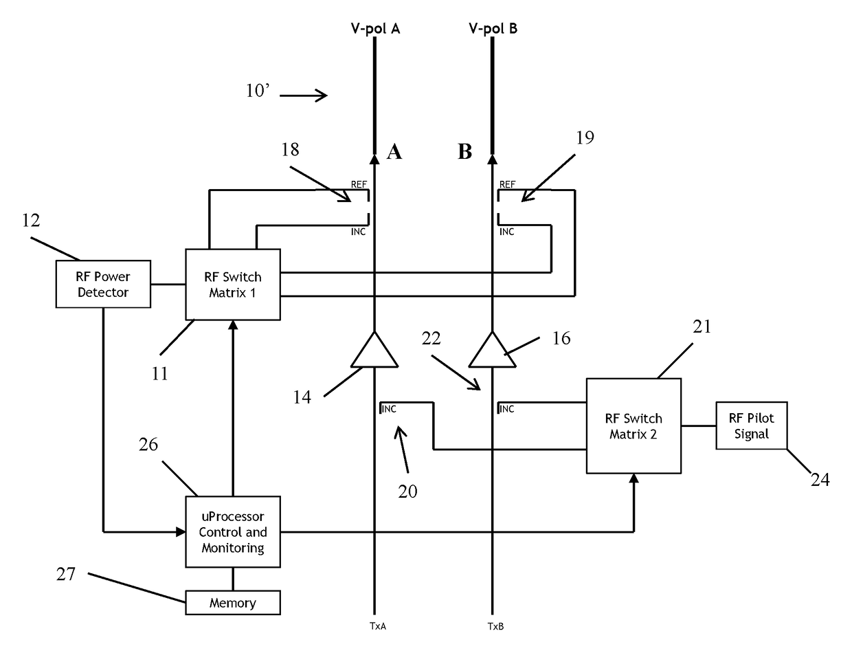
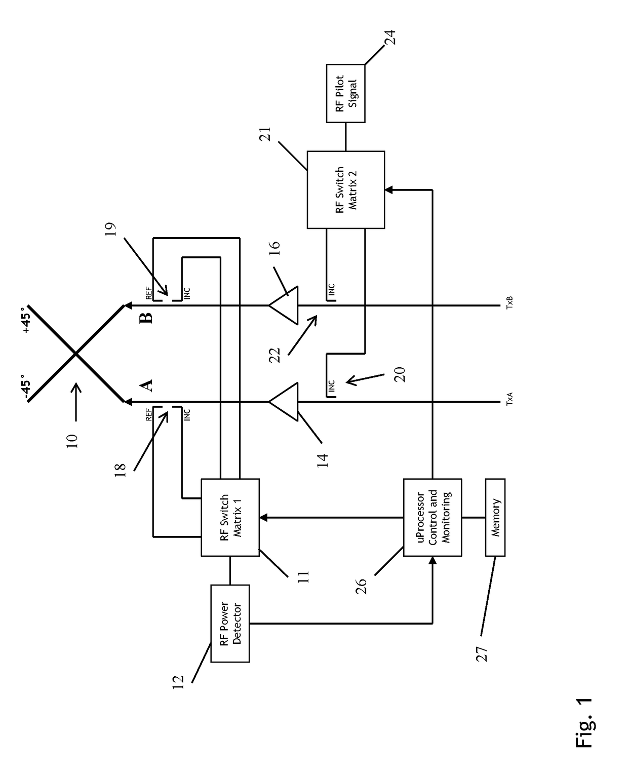
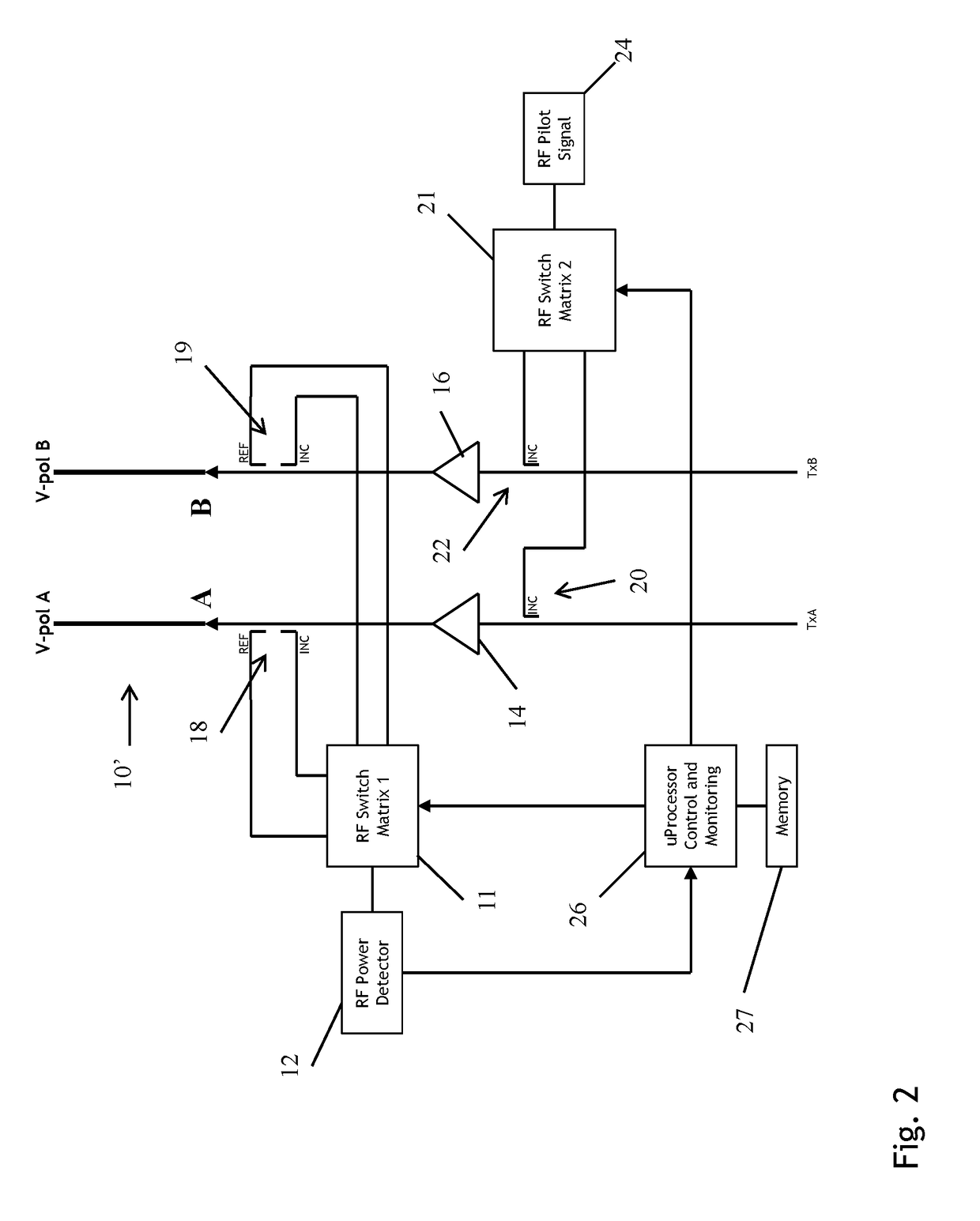
[0019]Described below are two internal measuring methods for determining whether each array element is properly connected to the respective transceiver. Each array element typically consists of two orthogonally polarized radiating elements, typically 90 degrees apart from each other, as in a cross-polarized (x-pol) or horizontal-vertical polarized (HV-pol) element. Each pair of orthogonally polarized elements is self-tested by performing a return loss measurement on each individual radiating element and by performing a cross element gain measurement in each direction.

[0020]In general, to perform a return loss measurement, a signal is transmitted to a radiating element. Part of that signal is reflected back toward the transmitter based on the return loss or VSWR (Voltage Standing Wave Ratio) of the radiating element. (Note that a VSWR measurement is a form of return loss measurement as both are based on measuring reflected power.) With the use of a dual-directional coupler placed at ...


PUM


Abstract

A method of testing a phased array antenna that includes a plurality of antenna element pairs, each antenna element pair of the plurality of antenna element pairs including a first antenna element and a second antenna element, the method including: for each antenna element pair of the plurality of antenna element pairs, performing a first cross element gain measurement from the first antenna element to the second antenna element of that antenna element pair; and determining whether there is a problem associated with the phased array antenna by examining the first cross element gain measurements for the plurality of antenna element pairs.

Description

CROSS REFERENCE TO RELATED APPLICATION[0001]This application claims the benefit of U.S. Provisional Application No. 62 / 326,099, entitled “Antenna Element Self-Test and Monitoring,” filed Apr. 22, 2016, all of which is incorporated herein by reference.TECHNICAL FIELD[0002]Embodiments of the present invention generally relate to testing active phased array antenna systems, and more specifically, to testing antenna elements in phased array antenna systems.BACKGROUND[0003]In a phased array antenna system, the array is typically a matrix of antenna elements where each element is connected to an individual transceiver. The transceivers are assembled and tested individually, as are the antenna elements. When the two are joined together after individual testing, there is a chance that one of the connections can bend, break, or present a poor RF connection for other reasons, such as poor soldering. Once the transceivers are joined with the antenna element array, discovering problems of this ...

Claims


Application Information

Patent Timeline
IPC IPC(8): H04B17/12H01Q21/22H01Q9/04H04B17/13H04B17/19H04B17/14H04B7/06H01Q11/20
CPCH04B17/12H01Q21/22H04B17/13H04B7/0608H01Q9/0478H01Q11/20H04B17/19H04B17/14H04B17/101H04B17/16H04B17/17H04B17/327
Inventor NARDOZZA, GREGG S.
Owner BLUE DANUBE LABS
Learn More