
Cyclone assembly for surface cleaning apparatus and a surface cleaning apparatus having same

a surface cleaning and assembly technology, applied in the direction of combination devices, applications, dispersed particle filtration, etc., can solve the problems of user's undesirable perception, pre-motor filter, clogging of particulate matter, etc., and achieve the effect of reducing backpressure and reducing backpressure through the cyclonic assembly

Active Publication Date: 2017-10-26
OMACHRON INTPROP
View PDF54 Cites 3 Cited by
  • Summary
  • Abstract
  • Description
  • Claims
  • Application Information

AI Technical Summary

Benefits of technology

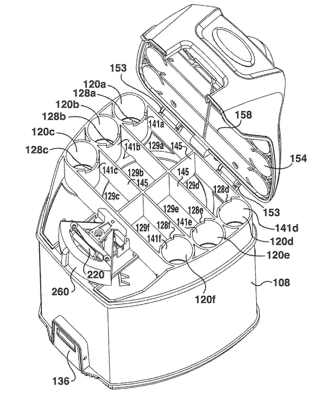
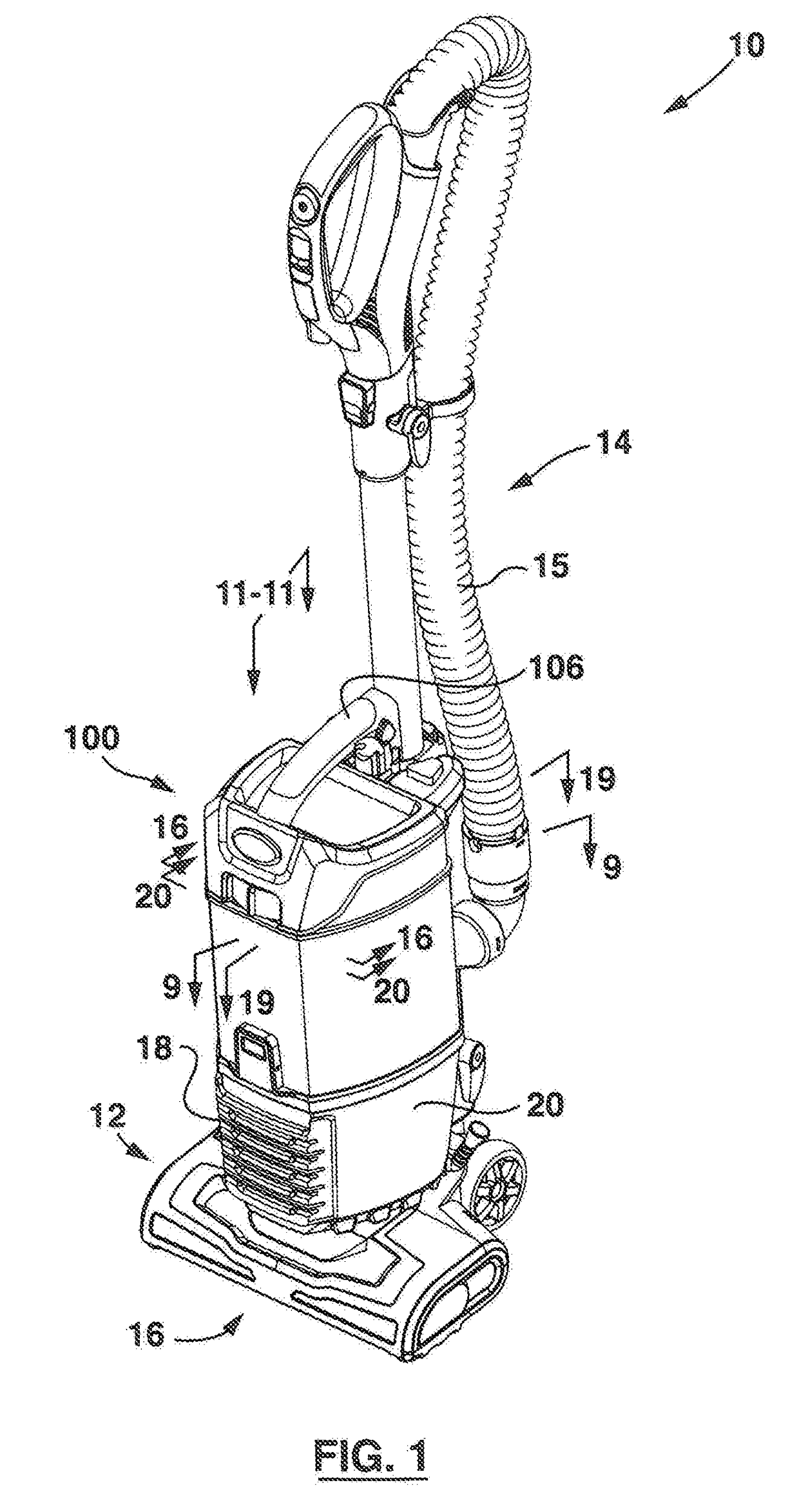
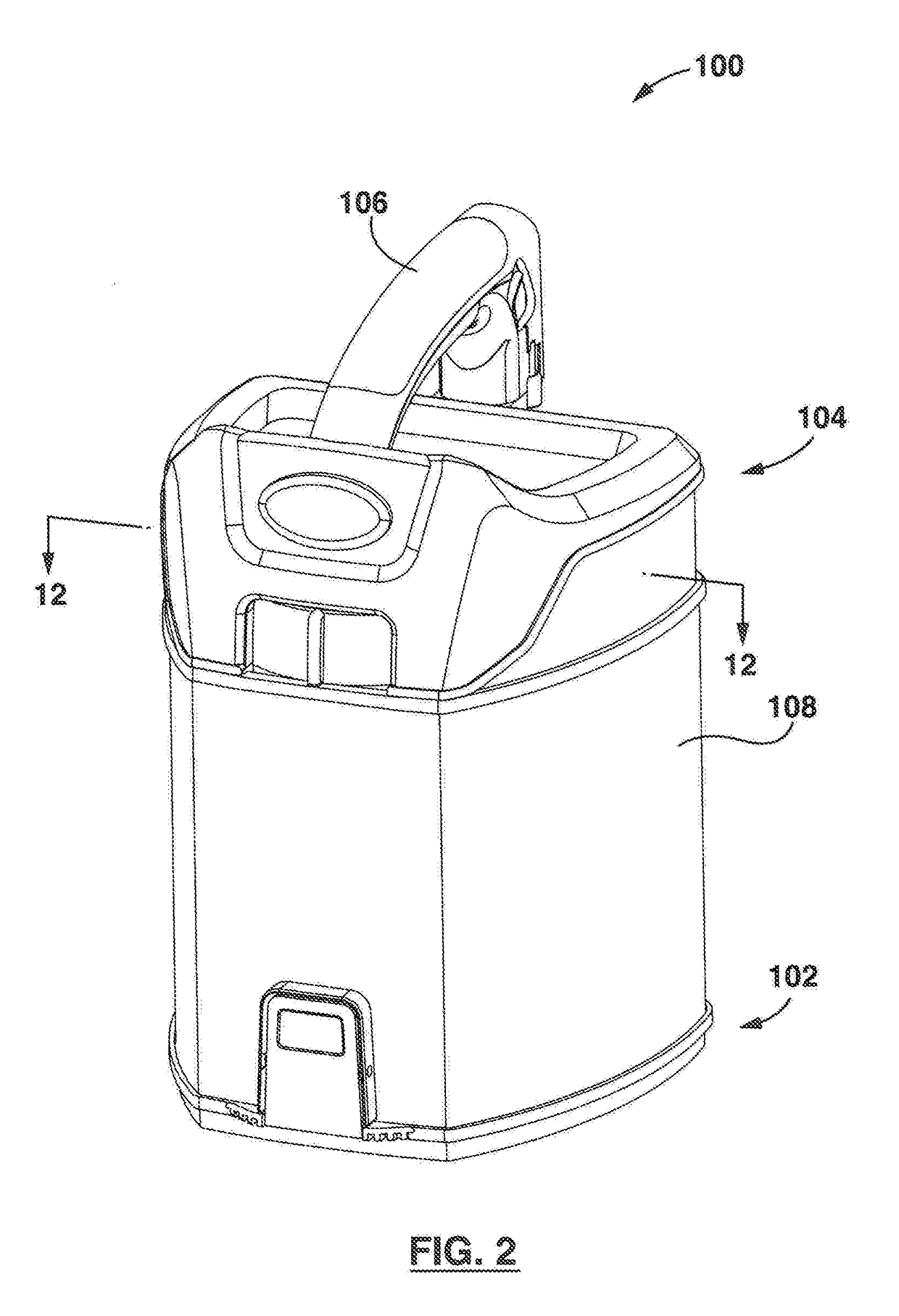
This patent describes a two-stage cyclone assembly for a surface cleaning apparatus that has a compact design and reduces backpressure. The assembly includes first and second cyclonic stages with a dirt collection region in between. The dirt collection region is located longitudinally above and overlying the first stage cyclone chamber, which simplifies the design and construction of the assembly. An upstream pre-motor filter chamber is positioned facing the second cyclonic cleaning stage, and the second stage cyclone air outlets have openings in a wall of the chamber. The design reduces the amount of conduit walls and ducting required, which may simplify the design and construction of the assembly and reduce backpressure. Overall, this compact design with two stages and reduced backpressure improves the performance and efficiency of surface cleaning apparatus.

Problems solved by technology

However, there may be one or more disadvantages associated with providing a pre-motor filter.
For example, the pre-motor filter may become clogged with particulate matter, requiring a user to clean and / or replace the filter, a task a user may regard as undesirable.
Otherwise, this unremoved particulate matter may cause damage to (or otherwise impair) the suction motor.
For example, the pre-motor filter may become clogged with particulate matter, requiring a user to clean and / or replace the filter, a task a user may regard as undesirable.

Method used


Image

  • Cyclone assembly for surface cleaning apparatus and a surface cleaning apparatus having same
  • Cyclone assembly for surface cleaning apparatus and a surface cleaning apparatus having same
  • Cyclone assembly for surface cleaning apparatus and a surface cleaning apparatus having same

Examples


Embodiment Construction

[0120]Various apparatuses, methods and compositions are described below to provide an example of an embodiment of each claimed invention. No embodiment described below limits any claimed invention and any claimed invention may cover apparatuses and methods that differ from those described below. The claimed inventions are not limited to apparatuses, methods and compositions having all of the features of any one apparatus, method or composition described below or to features common to multiple or all of the apparatuses, methods or compositions described below. It is possible that an apparatus, method or composition described below is not an embodiment of any claimed invention. Any invention disclosed in an apparatus, method or composition described below that is not claimed in this document may be the subject matter of another protective instrument, for example, a continuing patent application, and the applicant(s), inventor(s) and / or owner(s) do not intend to abandon, disclaim, or d...


PUM

PropertyMeasurementUnit
pressureaaaaaaaaaa
velocityaaaaaaaaaa
airflow velocitiesaaaaaaaaaa

Abstract

A cyclone assembly for a surface cleaning apparatus has a first cyclonic cleaning stage having a first end moveable between a closed position in which a first stage cyclone chamber and a first stage dirt collection chamber are closed and an open position in which the first stage cyclone chamber and the first stage dirt collection chamber are open, and a second cyclonic cleaning stage having a second end moveable between a closed position in which a plurality of second stage cyclone chambers and at least one second stage dirt collection chamber are closed and an open position in which the second stage cyclone chambers and the second stage dirt collection chamber are open.

Description

CROSS REFERENCE TO RELATED APPLICATIONS[0001]This application is a continuation-in-part of U.S. patent application Ser. No. 15 / 137,814, filed on Apr. 25, 2016, which is still pending, the disclosure of which is incorporated herein by reference in its entirety.FIELD[0002]This disclosure relates generally to cyclone assemblies for surface cleaning apparatus, and more specifically to cyclone assemblies that have first and second cyclonic cleaning stages.INTRODUCTION[0003]Various types of surface cleaning apparatus are known, including upright surface cleaning apparatus, canister surface cleaning apparatus, stick surface cleaning apparatus, hand carriable surface cleaning apparatus, and central vacuum systems.[0004]Surface cleaning apparatus that use one or more cyclonic cleaning stages to remove particulate matter (e.g. dust and dirt) from an airstream are known.[0005]A second cyclonic cleaning stage, which may comprise a plurality of cyclones in parallel, may be provided downstream of...

Claims


Application Information

Patent Timeline
Patent Type & Authority Applications(United States)
IPC IPC(8): A47L9/16B04C5/26B04C5/185B04C5/28
CPCA47L9/1633A47L9/1641A47L9/1608B04C5/185B04C5/26B04C5/28A47L9/1683A47L5/30A47L5/32A47L9/22B01D46/16B01D45/12B01D50/20
Inventor CONRAD, WAYNE ERNESTPETERSEN, DAVE
Owner OMACHRON INTPROP
Learn More