
Interior channel cable and tube management bracket

a technology for managing brackets and cable management, which is applied in the direction of pipe supports, machine supports, electrical equipment, etc., can solve the problems of inefficiency in the installation of such cabling and wiring, increased labor costs for cabling and wiring installation, and labor-intensive and time-consuming steps, so as to facilitate threading of cable tie threads, enhance stability and support for cables, and increase surface area contact

Inactive Publication Date: 2017-10-12
UNITED LAUNCH ALLIANCE
View PDF2 Cites 10 Cited by
  • Summary
  • Abstract
  • Description
  • Claims
  • Application Information

AI Technical Summary

Benefits of technology

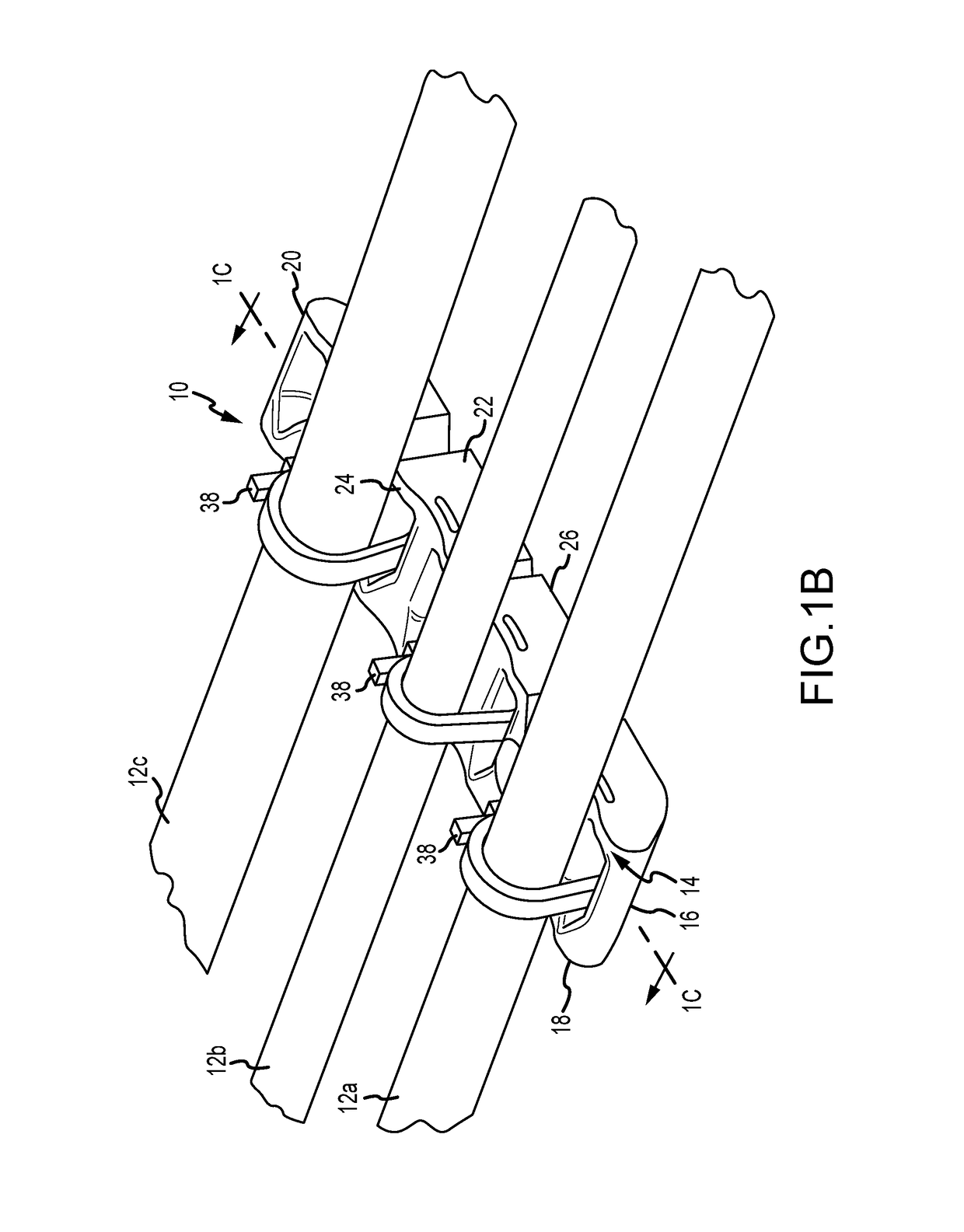
The present invention provides a cable bracket that overcomes the problems associated with currently available brackets by simplifying the installation process and reducing installation time and cost. The cable bracket has a multi-sided body with a cable tie passageway and a continuous passageway surface that allows for easy threading of a cable tie. The cable support member is positioned between the passageway openings and is contoured to provide increased stability and support for the cable. The cable bracket also has one or more recesses formed in one side that enclose a portion of each recess to assist in defining a cable tie passageway subtending the cable support member.

Problems solved by technology

Traditional cabling and wiring harnesses, cable tie mounts or brackets, by virtue of their construction or design, give rise to inefficiencies in the installation of such cabling and wiring.
Use of such traditional bracket hardware is labor intensive and, as a result, installation of cabling and wiring includes an increased labor cost.
Both steps are labor intensive and time consuming.
Also clamp-style brackets typically have a high cost due to a high part count including bolts, spacers and washers.
Clamp style brackets are also inflexible due to specific diameter sizing, requiring an inventory of differently sized clamp-style brackets for use with differently sized cabling.
This is a labor intensive process.
Further, comb brackets typically cannot be utilized with hard tubing due to the effects of vibration.
This, in turn, can result in failure of the bracket, tube or fastener.
Often, the surface area of the top of the pedestal is small compared to the size of the cable and provides little support for the cable.

Method used


Image

  • Interior channel cable and tube management bracket
  • Interior channel cable and tube management bracket
  • Interior channel cable and tube management bracket

Examples


Embodiment Construction

[0037]Those of skill in the art will recognize that the following description is merely illustrative of the principles of the invention, which may be applied in various ways to provide many different alternative embodiments. This description is made for illustrating the general principles of the teachings of this invention and is not meant to limit the inventive concepts disclosed herein. The detailed description is to be construed as exemplary only and does not describe every possible embodiment since describing every possible embodiment would be impractical, if not impossible. Numerous alternative embodiments could be implemented, using either current technology or technology developed after the filing date of this patent, which would still fall within the scope of the claims.

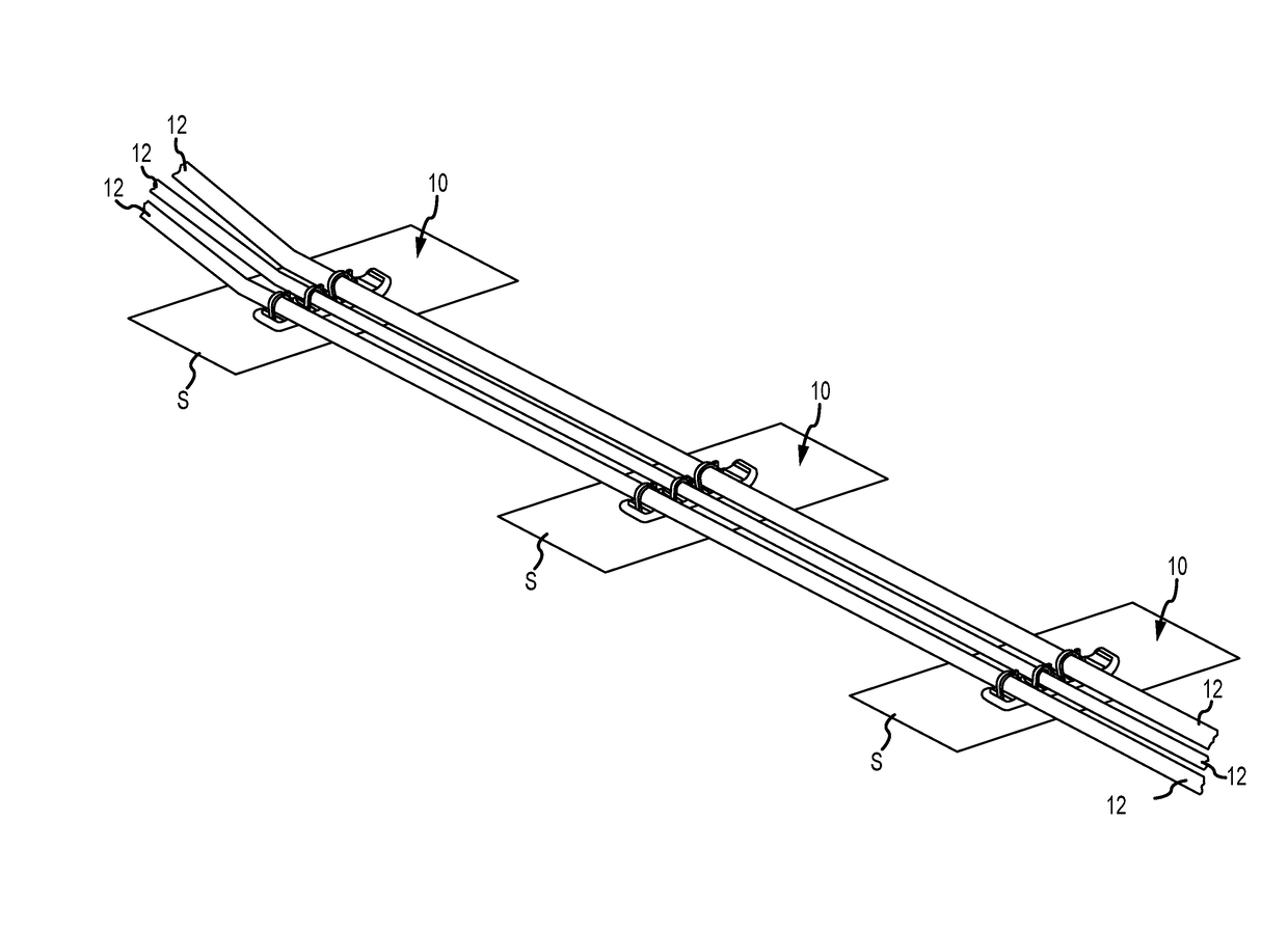
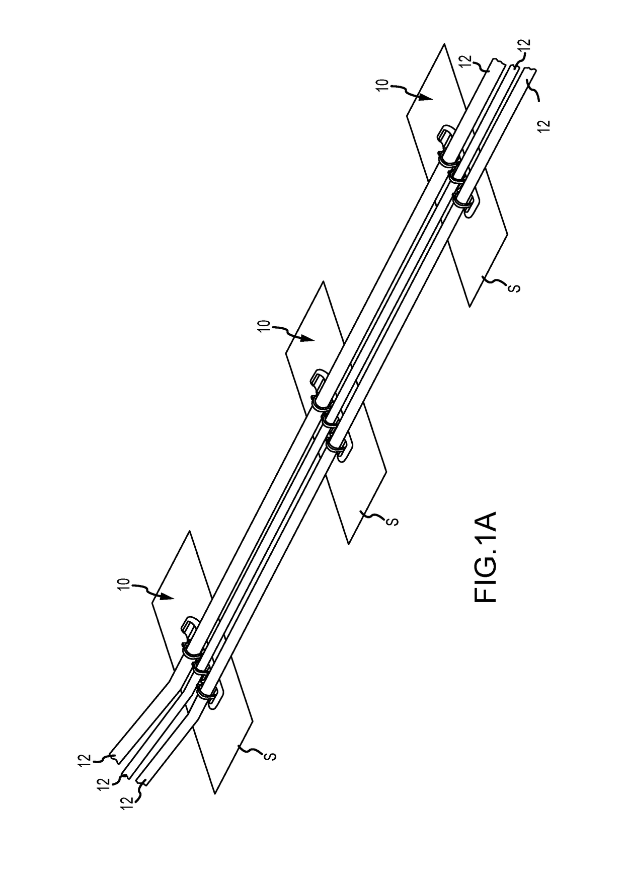
[0038]Turning to FIG. 1A, a series of brackets 10 are shown in spaced relation supporting and securing a plurality of cables 12. The brackets or harnesses 10 are secured to associated structural components S ...


PUM


Abstract

A cable bracket having at least one cable support member and a subtending continuous fastener passageway with a first open end and a second open end spaced from the first open end is disclosed. The first and second open ends are oriented on the same side of the cable bracket to facilitate installation.

Description

CROSS-REFERENCE TO RELATED APPLICATIONS[0001]This application claims the benefit of U.S. Provisional Patent Application Ser. No. 62 / 319,730, filed Apr. 7, 2016, the entirety of which is incorporated herein by reference.FIELD OF THE INVENTION[0002]The present disclosure relates to support structures or brackets for securing and organizing cable, optical and / or electrical wiring, fluid lines, and other flexible or rigid tubular structures.BACKGROUND OF THE INVENTION[0003]Traditional cabling and wiring harnesses, cable tie mounts or brackets, by virtue of their construction or design, give rise to inefficiencies in the installation of such cabling and wiring. Use of such traditional bracket hardware is labor intensive and, as a result, installation of cabling and wiring includes an increased labor cost. Therefore, an opportunity exists to reduce cost through improvements in cable brackets that reduce cabling and wiring installation time.[0004]One example of a traditional support struct...

Claims


Application Information

Patent Timeline
IPC IPC(8): F16L3/22F16L3/02F16M13/02F16L3/06
CPCF16L3/22F16M13/02F16L3/02F16L3/06F16L3/227H02G3/30H02G3/32
Inventor NGUYEN, ANTHONY PAUL
Owner UNITED LAUNCH ALLIANCE
Learn More