
Project management system for worksite including machines performing operations and method thereof

a project management system and worksite technology, applied in the field of project management system, can solve the problems of inability to provide expected output of the machine deployed at the worksite, factors affecting, and inability to easily determine the optimal output, so as to improve the productivity of the machin

Inactive Publication Date: 2017-10-05
CATERPILLAR INC
View PDF3 Cites 7 Cited by
  • Summary
  • Abstract
  • Description
  • Claims
  • Application Information

AI Technical Summary

Benefits of technology

This patent describes a system and method for managing a machine performing operations at a worksite. The system collects data about the machine's operations and the nature of the worksite, and uses that data to determine the machine's duty cycle (the amount of work it performs in a given period of time). The system then categorizes the machine's operations based on its duty cycle, providing resources to improve its productivity. The technical effect of this patent is to optimize machine performance and productivity at worksites through advanced analysis and classification of machine operations and resources.

Problems solved by technology

Sometimes, the machines deployed at the worksite may not be able to provide an expected output due to various factors.
The factors affecting, maximizing output may not be easily determined due to complexities involved in locations of the worksite, numerous machines operating at the worksite, numerous operators operating the machines, continuous operations at the worksite, etc.
The inefficiency may be due to, the machines operating at the worksite may not be a right fit for the type of operation, the incompatibility of work tools used in the machines, or specification or kind of machine may not be compatible with the machine's operation.
This may lead to lower productivity of the machines, and thus generally affect the productivity of the operation.
Though the recommendations may help to improve the overall productivity of the operation, time required to manually analyze the data may not be feasible and the provided recommendations may not always be completely accurate because of possibility of human error in the process.
Also, the recommendations, in general, have a limited scope because of limited resources for analysis of such large volumes of data involved.

Method used


Image

  • Project management system for worksite including machines performing operations and method thereof
  • Project management system for worksite including machines performing operations and method thereof
  • Project management system for worksite including machines performing operations and method thereof

Examples


Embodiment Construction

[0013]Reference will now be made in detail to specific aspects or features, examples of which are illustrated in the accompanying drawings. Wherever possible, corresponding or similar reference numbers will be used throughout the drawings to refer to the same or corresponding parts.

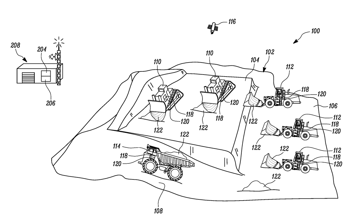
[0014]FIG. 1 illustrates a work environment 100 including a worksite 102, in which different kinds of machines are being operated, according to an exemplary embodiment of the present disclosure. The illustrated example shows machines including, but not limited to, track type tractors 110, wheel loaders 112, and a mining truck 114. Although only three kinds of machines are shown herein, it is to be understood that the type and number of machines shown are merely exemplary, and should not be construed as limiting this disclosure. For example, the machines may also include other kinds of machines including, but not limited to, an articulated truck, an on-road vehicle, an off-road vehicle, an excavator, a mot...


PUM


Abstract

A project management system for a worksite including a machine performing an operation therein is provided. The project management system includes a collection unit configured to collect data associated with at least one of the operation of the machine at the worksite and nature of the worksite. The project management system further includes a controller in communication with the collection unit. The controller is configured to receive the data from the collection unit. The controller is further configured to analyze the data to determine a duty cycle of the machine. The controller is further configured to classify the operation of the machine based on the duty cycle. The controller is further configured to provide one or more resources for improving a productivity of the machine based on the classification.

Description

TECHNICAL FIELD[0001]The present disclosure generally relates to a project management system, and more particularly relates to a project management system for improving productivity of an operation in a worksite having multiple machines therein.BACKGROUND[0002]Typically heavy machinery also referred to as ‘machines’, are deployed at multiple locations of a worksite based on the type of operations involved. The various operations of the machines may be controlled either manually by the operator or automatically by controlling the machines through a remote station. Sometimes, the machines deployed at the worksite may not be able to provide an expected output due to various factors. The factors affecting, maximizing output may not be easily determined due to complexities involved in locations of the worksite, numerous machines operating at the worksite, numerous operators operating the machines, continuous operations at the worksite, etc. The inefficiency may be due to, the machines op...

Claims


Application Information

Patent Timeline
IPC IPC(8): E02F9/26G06Q10/06G07C5/08E02F9/20G07C5/00
CPCE02F9/268E02F9/205G06Q10/0639G07C5/008G07C5/0808E02F9/2054E02F9/261
Inventor JENSEN, JEFFREY E.
Owner CATERPILLAR INC
Learn More