Container Storage Facility

a technology for storage facilities and containers, applied in the direction of conveyors, storage devices, basic electric elements, etc., can solve the problems of increasing the manufacturing cost of gas supply devices, increasing affecting the contents of containers in storage sections, etc., to achieve the reduction of the number of mass flow controllers that have to be installed, the effect of reducing the manufacturing cost and facilitating installation

Active Publication Date: 2017-10-05
DAIFUKU CO LTD
View PDF0 Cites 3 Cited by
  • Summary
  • Abstract
  • Description
  • Claims
  • Application Information

AI Technical Summary

Benefits of technology

The patent describes a way to reduce the manufacturing costs of a gas supplying device by using a mass flow controller in the second supply line. This reduces the number of mass flow controllers required and prevents the containers from being affected by the heat from the mass flow controller. Additionally, placing the mass flow controller in a different area from the storage sections reduces the risk of damage to the containers.

Problems solved by technology

The mass flow controllers are installed in the storing area in which the storage sections are installed in the conventional container storage facility described above; thus, when the temperature of a mass flow controller rises, the rise in the temperature may affect the container stored in the storage section, and in particular, the contents of the container.
Thus, many mass flow controllers have to be installed in the facility, contributing to an increase in the manufacturing cost of the gas supplying device.

Method used


Image

  • Container Storage Facility
  • Container Storage Facility
  • Container Storage Facility

Examples


first embodiment

[0016]The first embodiment of a container storage facility is described with reference to the attached drawings.

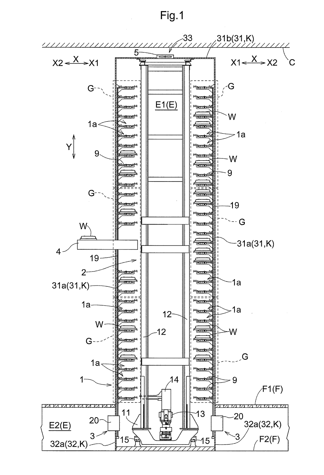
[0017]As shown in FIG. 1, the container storage facility has storage racks 1 configured to store containers W, a stacker crane 2 configured to transport containers W one container W at a time, and gas supplying devices 3. In addition, the container storage facility has walls K that cover the sides of the storing area E1 in which the storage racks 1 and the stacker crane 2 are installed, and transport conveyors 4 each configured to transport the containers W and so installed that each extends through a wall K. The walls K collectively form a wall assembly.

[0018]Each storage rack 1 has a plurality of storage sections 1a each of which can store a container W. Each gas supplying device 3 is configured to supply clean dry air (referred to simply hereinafter as “dry air”) as gas to inside of the containers W stored in the storage sections 1a. In other words, the gas supplied to ...

second embodiment

[0055]The second embodiment of the article transport facility in accordance with the present invention is described next with reference to FIG. 5.

[0056]The description of the second embodiment below will focus mainly on features and structures that are different from those of the first embodiment, such as the shape formed by the walls K, and locations of the mass flow controllers 20, etc. And description will be omitted for features and structures that are identical to those in the first embodiment.

[0057]The ceilings C of a clean room includes an upper ceiling portion C1 and a lower ceiling portion C2 installed below the upper ceiling portion C1. The upper ceiling portion C1 is a ceiling which does not have holes for allowing air to pass through. The lower ceiling portion C2 is a ceiling which allows air to pass through along the vertical direction Y. In the present embodiment, the upper ceiling portion C1 is formed of concrete without through holes. The lower ceiling portion C2 is ...


PUM


Abstract

A gas supplying device has a plurality of connectors each of which is configured to be connected to a container stored in the corresponding one of supplying storage sections, supply lines configured to divide and supply gas to the plurality of connectors, and a mass flow controller configured to control a flow rate of gas that flows through one of the supply lines. The supply lines include first supply lines each of which is installed to a corresponding supplying storage sections, a second supply line installed upstream of the first supply lines, and a branching supply line for dividing gas supplied from the second supply line into the first supply lines. The mass flow controller is installed in the second supply line and in an installation area.

Description

CROSS-REFERENCE TO RELATED APPLICATIONS[0001]This application claims priority to Japanese Patent Application Nos. 2016-070793 and 2016-139587, filed Mar. 31, 2016 and Jul. 14, 2016, respectively, the disclosures of which are hereby incorporated in their entirety by reference.FIELD OF THE INVENTION[0002]The present invention relates to a container storage facility comprising a plurality of storage sections which are installed in a storing area and each of which is configured to store a container, a gas supplying device configured to supply gas to inside of containers stored in supplying storage sections, with a part or all of the plurality of storage sections in the storing area being the supplying storage sections, wherein the gas supplying device has a plurality of connectors each of which is installed to a corresponding one of the supplying storage sections and is configured to be connected to a container stored in the corresponding one of the supplying storage sections, supply li...

Claims


Application Information

Patent Timeline
IPC IPC(8): B65G1/04H01L21/677F17D3/01
CPCB65G1/0407F17D3/01B65G2249/02H01L21/67751H01L21/67766H01L21/67393H01L21/67769F17C2221/031F17C2223/0123
Inventor KAWAMURA, SHINSUKEYOSHIMOTO, TADAHIRO
Owner DAIFUKU CO LTD
Why Eureka
Try Eureka