Space vector modulation for matrix converter and current source converter

a technology of current source converter and space vector, which is applied in the field of space vector modulation (svm), can solve the problems of large thd, inability to provide infinite load-side inductance lsub>, and in practice, and achieve the effect of improving svm

Active Publication Date: 2017-09-28
MURATA MFG CO LTD
View PDF4 Cites 12 Cited by
  • Summary
  • Abstract
  • Description
  • Claims
  • Application Information

AI Technical Summary

Benefits of technology

[0035]5) Improved SVM is simple and is capable of being calculated in real time.

Problems solved by technology

The problem with using known SVM with DCM is large THD, as shown in FIG. 10E.
It is impossible to provide an infinite load-side inductor Lo in practice.
Although it is possible to provide a load-side inductor Lo with a very large inductance, doing so requires providing a large inductor that makes design difficult.
It is impractical to assume that a power converter will only be used in CCM operation in any application that includes light-load conditions in which the power converter can be in DCM operation.
If the inductor current iL has ripples, the dwell time calculation based on these equations is not accurate.
The larger the ripple, the larger the error will be.
A large load-side inductance has the problems of large size, excessive weight, and high loss, for example.
The current ripple in a practical inductor also has the problems in modulation signals using traditional SVM, including increased line-side THD.
In addition, DCM is unavoidable when the load varies.

Method used


Image

  • Space vector modulation for matrix converter and current source converter
  • Space vector modulation for matrix converter and current source converter
  • Space vector modulation for matrix converter and current source converter

Examples


case 1

[0063] when the inductance Lo>∞ or the inductance Lo is so large that the current ripple can be ignored so that iL0=iL2=iL4=iL6−IL, then the dwell times are the same as the known SVM.

Tα=mTs sin(π / 6−θ)   (22)

Tβ=mTs sin(π / 6+θ)   (23)

T0=Ts−Tα−Tβ  (24)

where the modulation index m is given by:

m=kIrefIL,(25)

and θ is the angle between the reference current {right arrow over (I)}ref and the α-axis as shown in FIG. 7.

[0064]In this case, the improved SVM according to various preferred embodiments of the present invention is consistent with the known SVM.

case 2

[0065] When the inductance Lo is very small or the load is very light, then the load-side can be in DCM mode. The dwell times are calculated as:

Tα=2kIrefLoTssin(π / 6-θ)u1α / k-uo(26)Tβ=2kLoIrefTssin(π / 6+θ)β1β / k-uo(27)T0=Ts-Tα-Tβ(28)

where k is the transformer turns ratio, Lo is the inductance of the load-side inductor L0, {right arrow over (I)}ref is the magnitude of the vector {right arrow over (I)}ref and is determined by the controller, Ts is the sampling period, θ is the angle between the reference current {right arrow over (I)}ref and the a-axis as shown in FIG. 7, u1α is measured by the controller and corresponds to a line-to-line voltage depending on the switching state, u1β is measured by the controller and corresponds to a line-to-line voltage depending on the switching state, and uo is the output voltage as measured by the controller. The line-to-line voltages u1α and u1β depend on the switching state. For example, in Sector I with active vectors {right arrow over (I)}1 and {r...

case 3

[0066] when in CCM operation and the current ripple cannot be ignored, then the dwell times are calculated as:

Tα=-B+B2+ACsin(π / 6-θ)A(29)Tβ=-B+B2+ACsin(π / 6-θ)A·sin(π / 6+θ)sin(π / 6-θ)(30)T0=Ts-Tα-Tβwhere(31)A=(4u1α / k-uo)+(4u1β / k-uo)sin(π / 6+θ)sin(π / 6-θ)(32)B=2nLoIL0-3uoTs / 2(33)C=2n2kLIrefTs(34)

where um is measured by the controller and corresponds to a line-to-line voltage depending on the switching state, u1β is measured by the controller and corresponds to a line-to-line voltage depending on the switching state, k is the transformer turns ratio, uo is the output voltage as measured by the controller, θ is the angle between the reference current {right arrow over (I)}ref and the α-axis as shown in FIG. 7, Lo is the inductance of the load-side inductor Lo, IL0 is the current through inductor Lo as measured by the controller at the beginning of the sampling period Ts, Ts is the sampling period, and Iref is the magnitude of the vector {right arrow over (I)}ref and is determined by the cont...


PUM


Abstract

A converter includes a transformer including primary windings and secondary windings, switches connected to the primary windings, an output inductor connected to the secondary windings, and a controller connected to the switches. The controller turns the switches on and off based on dwell times calculated using space vector modulation with a reference current {right arrow over (I)}ref whose magnitude changes with time.

Description

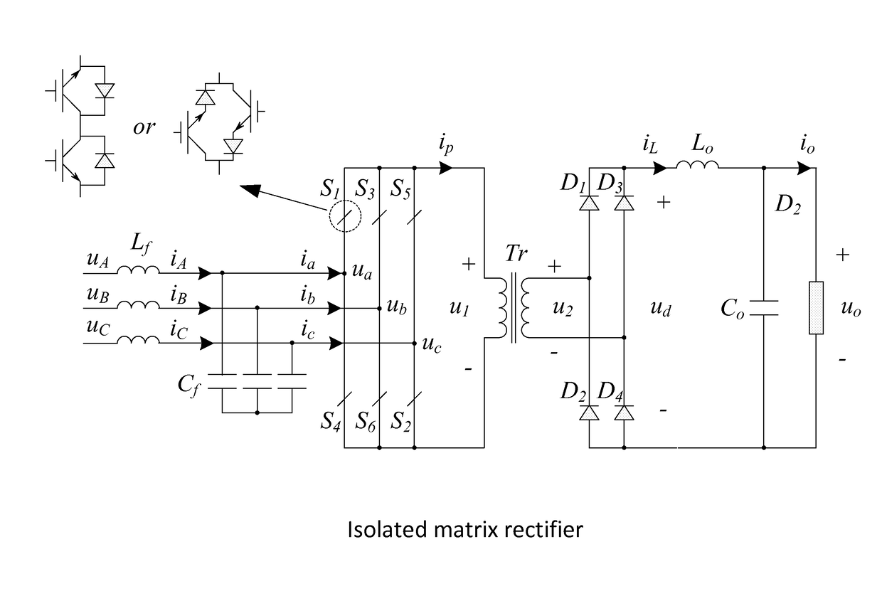
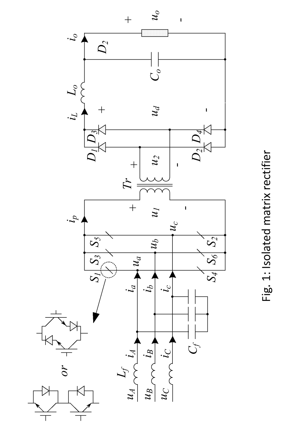
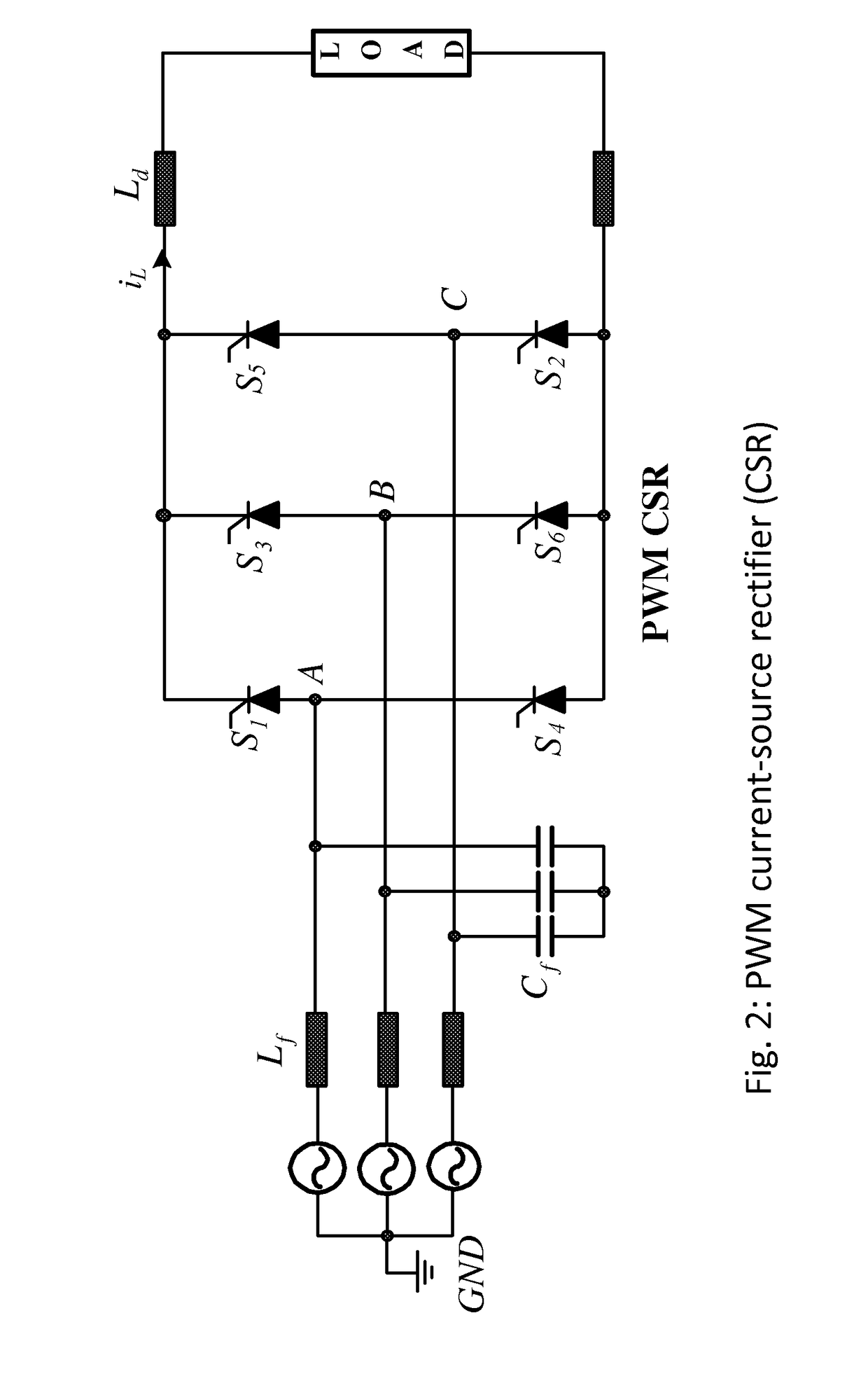
BACKGROUND OF THE INVENTION1. Field of the Invention[0001]The present invention relates to space vector modulation (SVM). More specifically, the present invention relates to an improved SVM algorithm that can be used with matrix rectifiers, current-source rectifiers, and current-source inverters.2. Description of the Related Art[0002]FIG. 1 shows an isolated matrix rectifier, FIG. 2 shows a current-source rectifier, and FIG. 3 shows a current-source inverter. Each of the circuits shown in FIGS. 1-3 can be used either with known SVM methods discussed in this section or with the novel SVM methods according to the preferred embodiments of the present invention discussed in the Detailed Description of Preferred Embodiments section below.[0003]In FIG. 1, “line side” refers to the portion of the circuit on the left-hand side of the transformer Tr that is connected to the line voltages ua, ub, uc for each of the phases A, B, C, and “load side” refers to the portion of the circuit on the ri...

Claims


Application Information

Patent Timeline
Patent Type & Authority Applications(United States)
IPC IPC(8): H02M7/162H02M5/297H02M5/293H02M7/527
CPCH02M7/1626H02M7/527H02M2007/53876H02M5/293H02M1/12H02M5/297H02M7/53876
Inventor ZHAO, TAOXU, DEWEIAFSHARIAN, JAHANGIRGONG, BINGYANG, ZHIHUA
Owner MURATA MFG CO LTD
Why Eureka
Try Eureka