Hydraulic breaker

a technology of hydraulic breaker and breaker body, which is applied in the field of hydraulic breaker, can solve the problems of reducing productivity, frequent breakage of control valve b>151/b>, and loud noise during operation, and achieves the effects of convenient replacement, shortening replacement time, and enhancing productivity

Inactive Publication Date: 2017-09-28
AYHEAVY IND
View PDF15 Cites 7 Cited by
  • Summary
  • Abstract
  • Description
  • Claims
  • Application Information

AI Technical Summary

Benefits of technology

[0016]Therefore, the present invention has been made in view of the above problems, and it is one object of the present invention to provide a hydraulic breaker including a conveniently replaceable control valve and having enhanced productivity due to shortened replacement time.
[0017]It is another object of the present invention to provide a hydraulic breaker in which a breaker main body is stably supported by a bracket, resulting in reduced noise during operation and enhanced work efficiency.The above and other objects can be accomplished by the present disclosure described below.
[0022]As is apparent from the foregoing description, a control valve is installed at a back head of a breaker main body, and thus the control valve may be conveniently replaced and productivity may be enhanced due to shortened replacement time.
[0023]In addition, a bracket has an improved support structure for the breaker main body, and thus the breaker main body is stably supported by the bracket, resulting in reduced occurrence of noise during operation and enhanced work efficiency.

Problems solved by technology

In particular, the control valve 151 frequently breaks down due to frequent hydraulic interruption.
Thus, replacement of the control valve 151 is inconvenient and takes a long time, resulting in reduced productivity.
Accordingly, the support member moves upward, downward, leftward, or rightward, and thus the breaker main body is not satisfactorily fixed, resulting in occurrence of loud noise during operation and reduced work efficiency.

Method used


Image

  • Hydraulic breaker
  • Hydraulic breaker
  • Hydraulic breaker

Examples


Embodiment Construction

[0029]Hereinafter, the present invention will be described in detail with reference to the accompanying drawings.

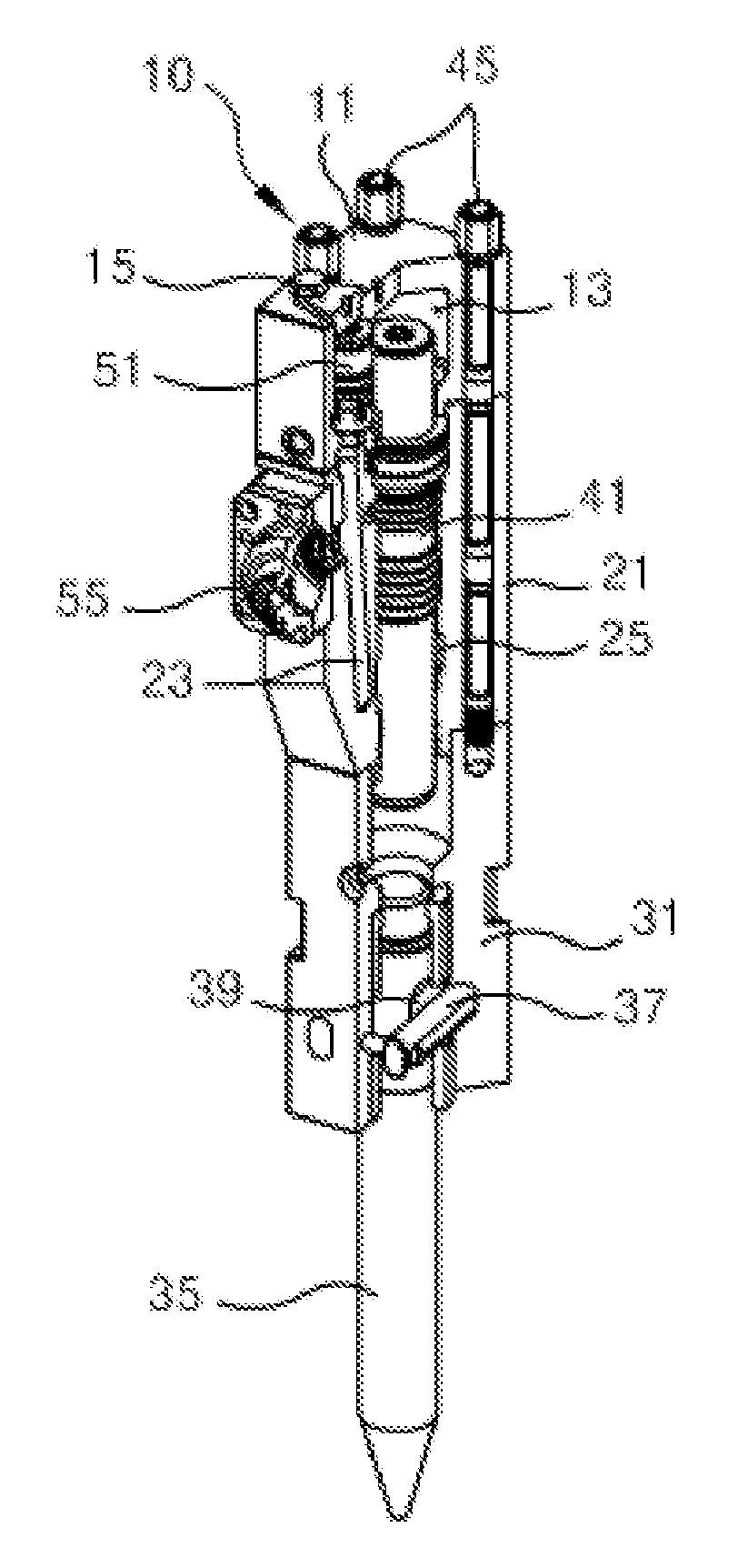
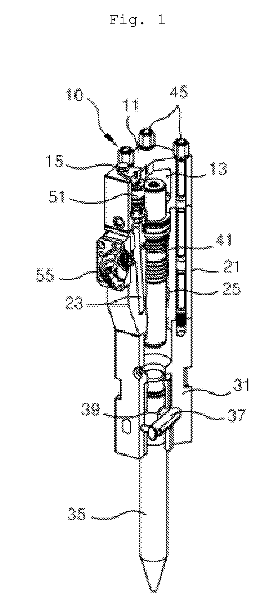
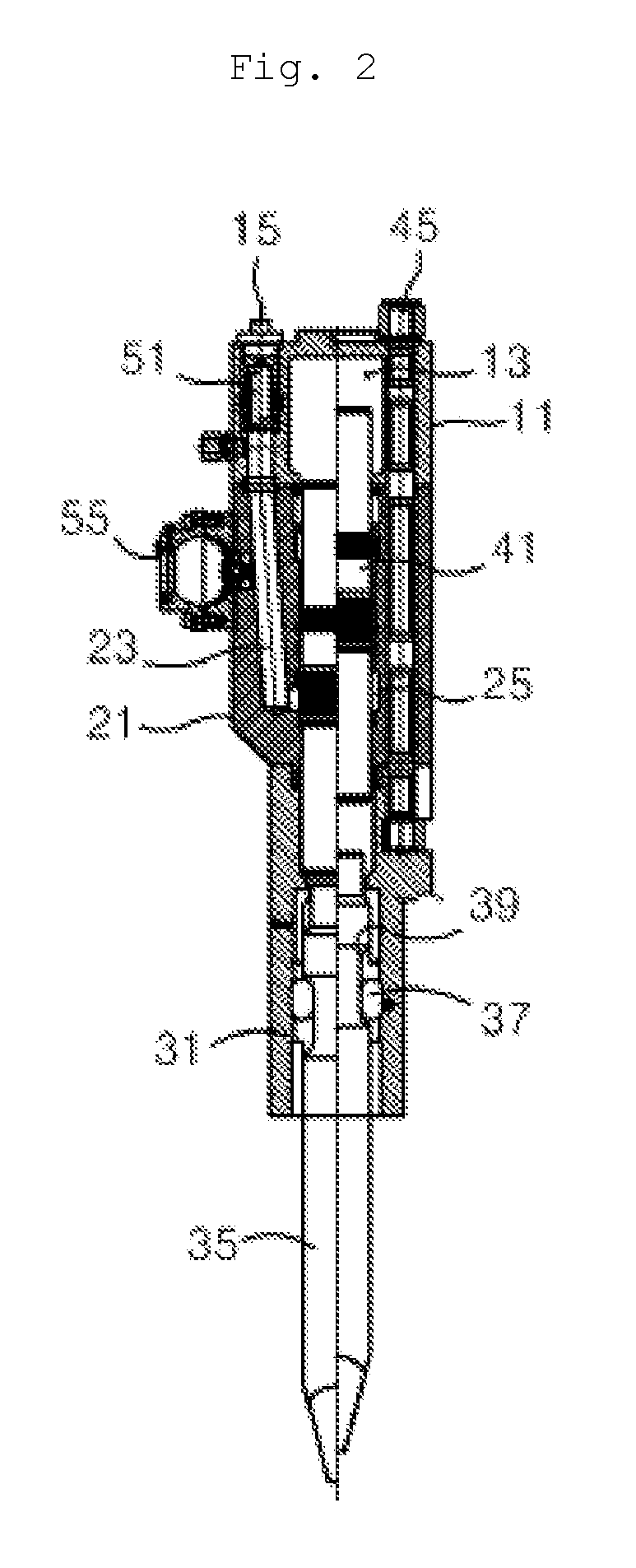
[0030]FIGS. 1 and 2 illustrate a breaker main body of a hydraulic breaker according to the present invention.

[0031]As illustrated in the drawings, the breaker main body 10 of a hydraulic breaker according to the present invention includes a back head 11, a cylinder 21, a front head 31, a chisel 35, and a piston 41. In this regard, to aid in understanding of an operation of the breaker main body 10, a left side cross-sectional view of FIG. 2 illustrates a state in which the chisel 35 of the breaker main body 10 is lowered, and a right side cross-sectional view of FIG. 2 illustrates a state in which the chisel 35 is raised.

[0032]The back head 11 is provided with a gas chamber 13 therein, and is positioned at the uppermost end of the breaker main body 10. The back head 11 is provided with a control valve 51 detachably, which will be described below, and is provided with a va...


PUM


Abstract

The present invention relates to a hydraulic breaker comprising: a back head having a gas chamber provided therein; a cylinder disposed at the lower part of the back head, and having a hydraulic passage and a hydraulic space; a front head disposed at the lower part of the cylinder; a chisel provided inside the front head; a piston provided to reciprocate in the cylinder so as to hit the chisel; and a breaker main body having a plurality of penetration bolts integrally connecting the back head, the cylinder, and the front head, wherein the back head of the breaker main body is provided with a control valve for supplying and blocking hydraulic pressure to / from the hydraulic passage and the hydraulic space.

Description

CROSS-REFERENCES TO RELATED APPLICATIONS[0001]This Application claims the benefit of priority and is a Continuation application of the prior International Patent Application No. PCT / KR2015 / 014350, with an international filing date of Dec. 28, 2015, which designated the United States, and is related to the Korean Patent Application No. 10-2015-0001775, filed Jan. 7, 2015, the entire disclosures of all applications are expressly incorporated by reference in their entirety herein.BACKGROUND OF THE INVENTION1. Field of the Invention[0002]The present invention relates to a hydraulic breaker, and more particularly, to a hydraulic breaker in which a control valve of a breaker main body has an improved installation structure.2. Description of Related Art[0003]Generally, hydraulic breakers are widely used to break rocks, concrete, and the like by being installed at excavators, which are construction machines.[0004]A breaker main body of such a conventional hydraulic breaker is illustrated in...

Claims


Application Information

Patent Timeline
Patent Type & Authority Applications(United States)
IPC IPC(8): B25D9/14E02F5/30E02F3/96B25D9/04
CPCB25D9/145B25D9/04B25D2250/125E02F3/966B25D2209/002E02F5/305B25D17/11B25D17/24B25D2250/065B25D2250/105B25D2250/121B25D2250/245
Inventor JEON, SUNG WOOK
Owner AYHEAVY IND
Why Eureka
Try Eureka