Apparatus and method for a tramp iron relief system

a tramp iron relief and cylinder technology, applied in the field of hydraulic tramp iron relief systems, can solve the problems of high production cost, high production cost, and high cost of conventional tir systems, and achieve the effects of reducing movement, limiting pressure, and reducing pressure in the rod end

Active Publication Date: 2017-09-28
KOLBERG PIONEER INC
View PDF4 Cites 6 Cited by
  • Summary
  • Abstract
  • Description
  • Claims
  • Application Information

AI Technical Summary

Benefits of technology

[0013]The apparatus of the invention comprises a tramp iron relief system for a jaw crusher having a movable jaw and a stationary jaw defining a crushing chamber for crushing aggregate material. The preferred tramp iron relief system comprises a tramp iron relief cylinder having a rod end and a base end and being adapted to limit pressure on the movable jaw of the jaw crusher when tramp iron is present in the crushing chamber. The preferred tramp iron relief cylinder is also adapted to receive oil to exert pressure on the movable jaw during crushing operations and includes a relief valve that is adapted to provide a quick discharge path for oil in the tramp iron relief cylinder when open. The preferred relief valve is also adapted to open when oil pressure within the tramp iron relief cylinder exceeds a pre-designated limit. The preferred tramp iron relief system also comprises a tramp iron relief cylinder manifold block that is adapted to control the flow of oil into and out of the tramp iron relief cylinder. The preferred tramp iron relief system further comprises a tension cylinder that is adapted to provide tension force to keep the tramp iron relief cylinder in operative contact with the movable jaw of the jaw crusher during crushing operations. The preferred tension cylinder is also adapted to receive oil. The preferred tramp iron relief system still further comprises a tension cylinder manifold block that is adapted to control the flow of oil into and out of the tension cylinder, a tank line accumulator that is adapted to receive and hold oil discharged from the tramp iron relief cylinder when the relief valve is open, and a hydraulic network to convey oil between the tank line accumulator, the tramp iron relief cylinder, and the tension cylinder.
[0014]The method of the invention comprises a method for reducing the movement of a tramp iron relief cylinder on a jaw crusher during normal operations. The preferred method comprises providing a tramp iron relief system for a jaw crusher having a movable jaw and a stationary jaw defining a crushing chamber for crushing aggregate material. The preferred tramp iron relief system comprises a tramp iron relief cylinder having a rod end and a base end and being adapted to release pressure on the movable jaw of the jaw crusher when tramp iron is present in the crushing chamber. The preferred tramp iron relief cylinder is also adapted to receive oil to exert pressure on the movable jaw during crushing operations and includes a relief valve that is adapted to provide a quick discharge path for oil in the tramp iron relief cylinder when open. The preferred relief valve is also adapted to open when oil pressure within the tramp iron relief cylinder exceeds a pre-designated limit. The preferred tramp iron relief system also comprises a tramp iron relief cylinder manifold block that is adapted to control the flow of oil into and out of the tramp iron relief cylinder. The preferred tramp iron relief system further comprises a tension cylinder that is adapted to provide tension force to keep the tramp iron relief cylinder in operative contact with the movable jaw of the jaw crusher during crushing operations. The preferred tension cylinder is also adapted to receive oil. The preferred tramp iron relief system still further comprises a tension cylinder manifold block that is adapted to control the flow of oil into and out of the tension cylinder, a tank line accumulator that is adapted to receive and hold oil discharged from the tramp iron relief cylinder when the relief valve is open, and a hydraulic line to convey oil between the tank line accumulator, the tramp iron relief cylinder, and the tension cylinder. The preferred method also comprises reducing the pressure in the rod end of the tramp iron relief cylinder during normal operations of the jaw crusher.
[0015]In order to facilitate an understanding of the invention, the preferred embodiments of the invention, as well as the best mode known by the inventor for carrying out the invention, is illustrated in the drawings, and a detailed description thereof follows. It is not intended, however, that the invention be limited to the particular embodiment described or to use in connection with the apparatus illustrated herein. Therefore, the scope of the invention contemplated by the inventor includes all equivalents of the subject matter recited in the claims, as well as various modifications and alternative embodiments such as would ordinarily occur to one skilled in the art to which the invention relates. The inventor expects skilled artisans to employ such variations as seem to them appropriate, including the practice of the invention otherwise than as specifically described herein. In addition, any combination of the elements and components of the invention described herein in any possible variation is encompassed by the invention, unless otherwise indicated herein or clearly excluded by context.

Problems solved by technology

Aggregate material fed into the crushing chamber from time to time includes uncrushable material, commonly known in the field as “tramp iron.” This tramp iron generally hinders or interrupts the operation of the jaw crusher and can cause damage to components of the jaw crusher.
For example, conventional TIR systems allow excessive movement of the tramp iron relief system cylinders during normal crushing operations.
Further, conventional TIR systems have a tendency to experience pressure spikes in the rod end of the tramp iron relief cylinders.
Moreover, conventional TIR systems are often expensive to produce, maintain, repair, and replace.

Method used


Image

  • Apparatus and method for a tramp iron relief system
  • Apparatus and method for a tramp iron relief system
  • Apparatus and method for a tramp iron relief system

Examples


Embodiment Construction

[0033]This description of preferred embodiments of the invention is intended to be read in connection with the accompanying drawings, which are to be considered part of the entire written description of this invention. The drawing figures are not necessarily to scale, and certain features of the invention may be shown exaggerated in scale or in somewhat schematic form in the interest of clarity and conciseness.

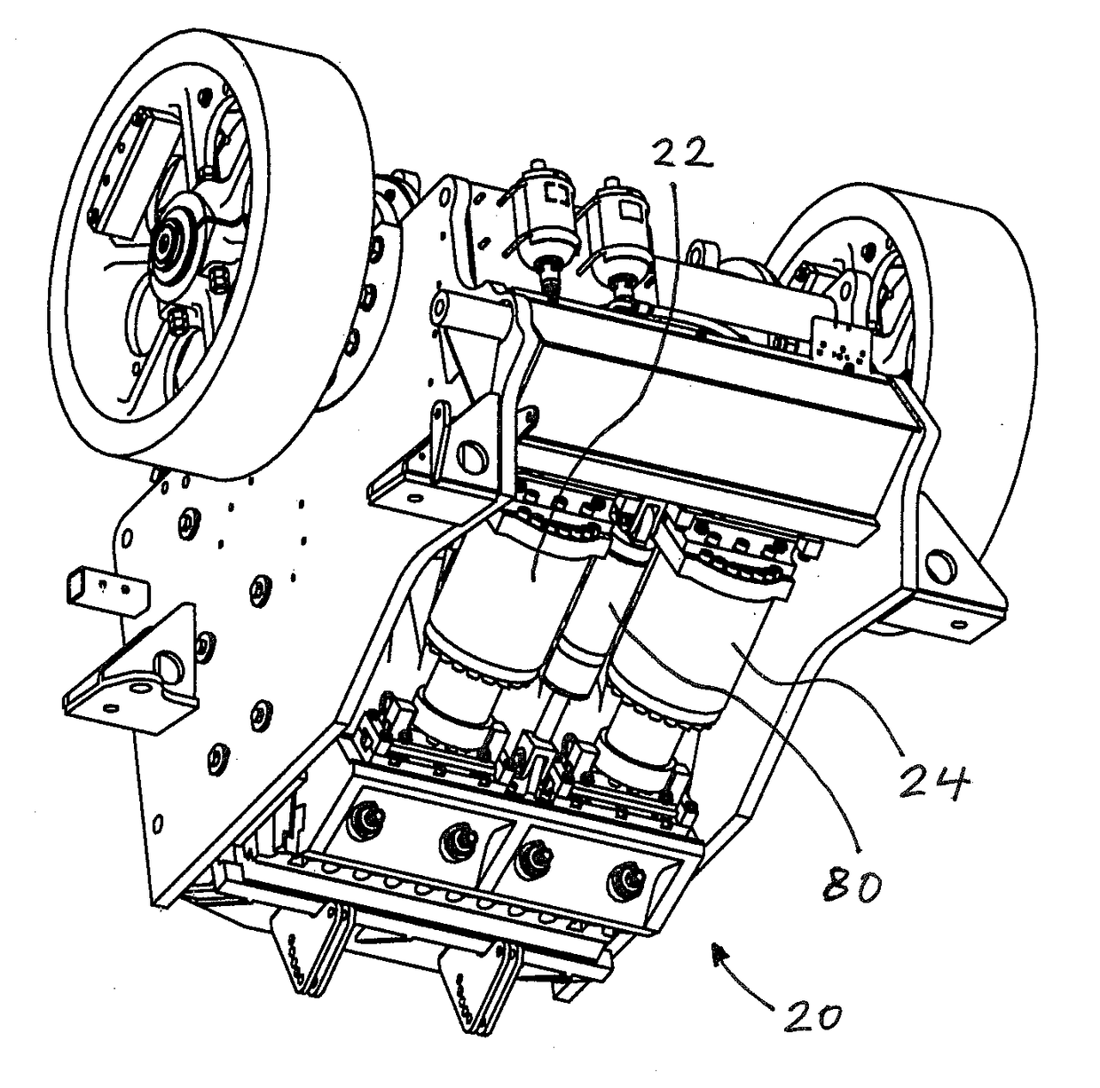
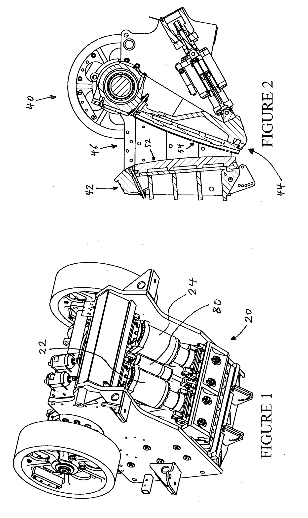
[0034]Referring now to the drawings, FIG. 1 is a perspective view of the preferred tramp iron relief system on an exemplary jaw crusher in accordance with the present invention. As shown in FIG. 1, the preferred tramp iron relief system is designated generally by reference numeral 20. Preferred tramp iron relief system 20 comprises tramp iron relief cylinders 22 and 24 and tension cylinder 80.

[0035]Referring now to FIG. 2, an example embodiment of a jaw crusher is illustrated. As shown therein, the exemplary jaw crusher is designated generally by reference numeral 40. Exemplar...


PUM


Abstract

A tramp iron relief system for a crusher. The preferred system includes a tramp iron relief cylinder, a relief valve adapted to open when oil pressure within said tramp iron relief cylinder exceeds a pre-designated limit, a tramp iron relief cylinder manifold block that is adapted to control the flow of oil into and out of the tramp iron relief cylinder, a tension cylinder, a tension cylinder manifold block adapted to control the flow of oil into and out of the tension cylinder, a tank line accumulator, and a hydraulic line to convey oil between the tank line accumulator, the tramp iron relief cylinder, and the tension cylinder. A method for controlling the movement of the tramp iron relief cylinder including reducing the pressure in the rod end of the tramp iron relief cylinder during normal operations of the crusher.

Description

CROSS-REFERENCE TO RELATED APPLICATION[0001]This application relates back to and claims the benefit of priority from U.S. Provisional Application for Patent Ser. No. 62 / 311,959, titled “Tramp Iron Relief System,” which was filed on Mar. 23, 2016.FIELD OF THE INVENTION[0002]The present invention relates generally to jaw crushers and, more particularly, to hydraulic tramp iron relief systems for jaw crushers.BACKGROUND AND DESCRIPTION OF THE PRIOR ART[0003]Jaw crushers or rock crushers (hereinafter generally “jaw crushers”) known in the art typically include a stationary jaw and a moveable jaw spaced apart to define between them a “crushing gap” or “crushing chamber.” As the moveable jaw reciprocates toward and away from the stationary jaw, aggregate material fed into the crushing chamber is crushed by crushing surfaces on each of the jaws to produce an aggregate product principally of a pre-determined size. Aggregate material fed into the crushing chamber from time to time includes u...

Claims


Application Information

Patent Timeline
Patent Type & Authority Applications(United States)
IPC IPC(8): B02C1/02B02C1/04B02C1/00
CPCB02C1/025B02C1/04B02C1/005B02C1/00B02C1/02
Inventor RUST, JOEENGEL, GARY
Owner KOLBERG PIONEER INC
Why Eureka
Try Eureka