
Dynamic virtual beacon methods and apparatus

Active Publication Date: 2017-09-21
JUNIPER NETWORKS INC
View PDF3 Cites 14 Cited by
  • Summary
  • Abstract
  • Description
  • Claims
  • Application Information

AI Technical Summary

Benefits of technology

The present invention provides methods and apparatus for updating virtual beacon transmitters easily without the need for physical modifications. The location and size of virtual beacon coverage areas can be changed based on factors such as the size of a group, physical distribution of the group, and rate of motion of the group. This flexibility allows for dynamic changes in virtual beacon transmission without the need for physical modifications.

Problems solved by technology

The placement, moves and maintenance of physical beacon transmitters can be costly to deploy, expensive to maintain and in the case of at least some transmitters, difficult to move.
In addition it can be difficult to change the transmit power and / or other physical characteristics of a physical transmitter given that some changes might require physical movement and / or changes to a beacon transmitter.

Method used


Image

  • Dynamic virtual beacon methods and apparatus
  • Dynamic virtual beacon methods and apparatus
  • Dynamic virtual beacon methods and apparatus

Examples


Embodiment Construction

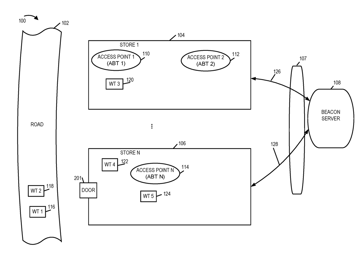
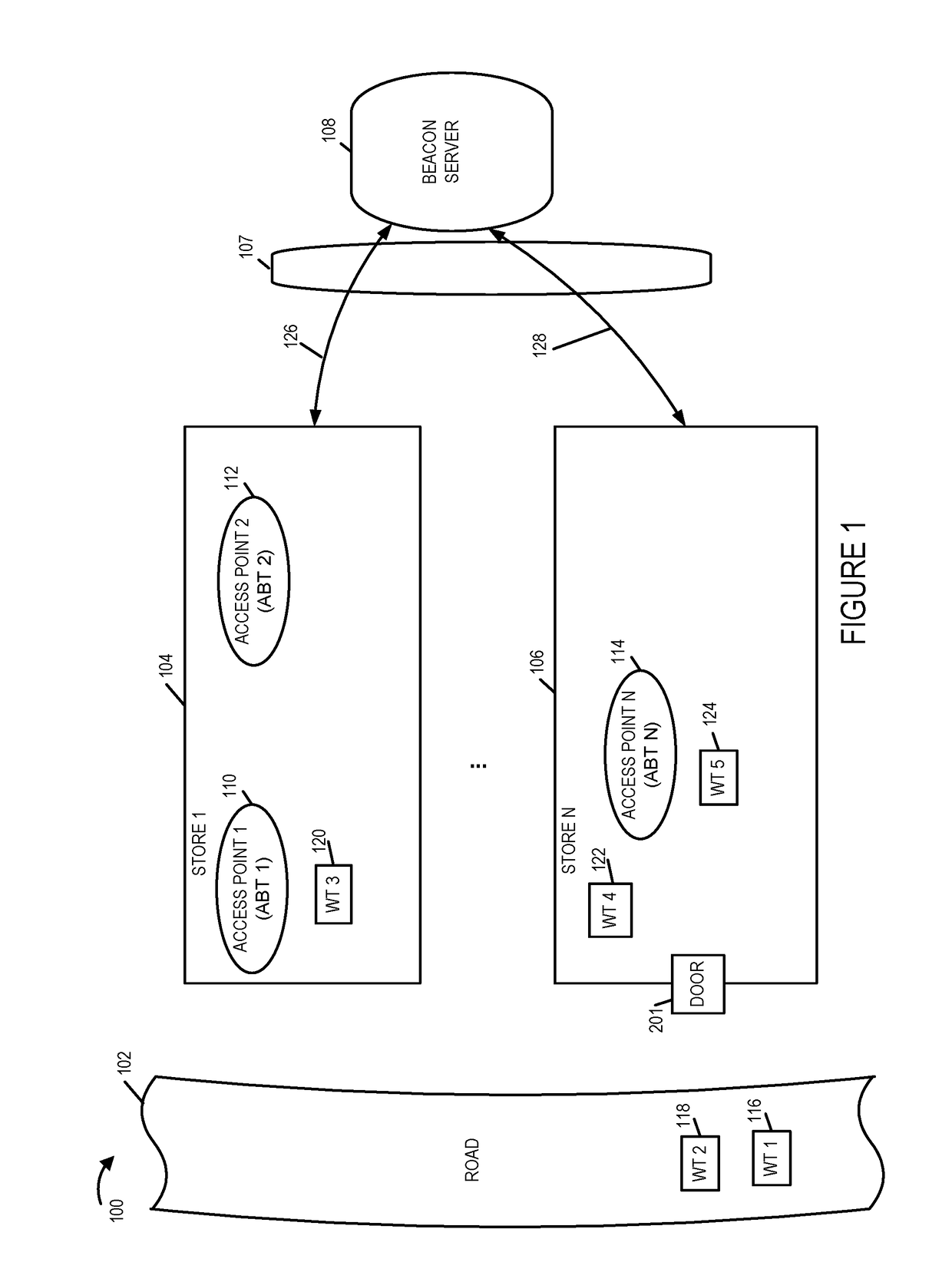
[0049]FIG. 1 is a drawing of an exemplary system and exemplary environment in accordance with one exemplary embodiment. FIG. 1 shows an environment 100 which includes a road 102 and multiple stores including a first store 104 and a Nth store 106. The environment 100 includes various user devices, e.g., wireless terminal (WT) 1116 and WT 2118 on the road 102. The wireless terminals may be cell phones or other wireless devices of individuals in separate cars traveling on the road 102. Adjacent the road are store 1104 and store N 106. Additional stores represented by the three dots may be located along the road.

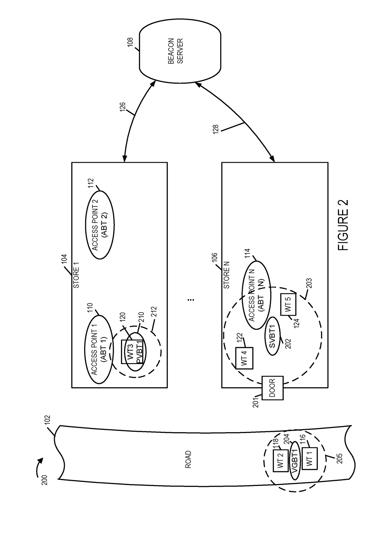
[0050]The first and Nth stores 104, 106 include access points 110, 112 and 114 which transmit beacon signals that can be detected by wireless terminals 120, 122, 124 in the stores and / or WT 1116 and WT 2118 passing along the road when they are within the transmission range of the access points. For example, wireless terminal WT3120 in store 1104 is within range of access point 1...


PUM


Abstract

Methods and apparatus relating to use of actual and / or virtual beacons are described. Virtual beacons are virtual in that an actual beacon need not be transmitted but a rather a virtual beacon transmitter at a desired location may be considered to transmit virtual beacons. Beacon transmitter information indicates transmission power and location of actual and virtual beacon transmitters as well as information to be communicated by virtual beacons and is dynamically updated based on device movement, a schedule and / or the locations of devices in a group. Virtual personal beacons, virtual group beacons and virtual scheduled beacons are supported. A virtual personal beacon transmitter location is updated as the location of a device corresponding to the person moves. Reception of a virtual beacon is reported in a message sent to a wireless terminal or a component of the wireless terminal which acts upon receiving an indication of beacon reception.

Description

RELATED APPLICATIONS[0001]The present application claims the benefit of U.S. Provisional Patent Application Ser. No. 62 / 197,980 filed Jul. 28, 2015 and is a continuation-in-part of U.S. patent application Ser. No. 14 / 811,684 filed Jul. 28, 2015, is a continuation-in-part of U.S. patent application Ser. No. 14 / 811,689 filed Jul. 28, 2015 and is a continuation-in-part of U.S. patent application Ser. No. 14 / 850,725 filed Sep. 10, 2015 which claims the benefit of U.S. Provisional Patent Application Ser. No. 62 / 155,428 filed Apr. 30, 2015, each of the above identified patent applications is hereby expressly incorporated in its entirety.FIELD[0002]The present application relates to wireless beacons and, more particularly, to methods and apparatus for using real and / or virtual beacon signals.BACKGROUND[0003]Physical beacon transmitters are used to transmit signals which can be used to communicate identifiers and / or information. A device receiving a beacon signal can use the information in ...

Claims


Application Information

Patent Timeline
IPC IPC(8): H04W48/08H04W16/28H04W72/08H04W4/02H04W4/029H04W4/33
CPCH04W48/08H04W72/085H04W16/28H04W4/025G01S5/0273G01S5/0278H04W52/242H04W64/00H04B17/27H04B17/318H04B17/373H04W4/029H04W72/542H04W4/33
Inventor FRIDAY, ROBERTCASTAGNOLI, NEAL DANTEFREI, RANDALL WAYNE
Owner JUNIPER NETWORKS INC
Learn More