Fuel pump with improved delivery properties

a technology of fuel pump and delivery mechanism, which is applied in the direction of piston pump, positive displacement liquid engine, combustion air/fuel air treatment, etc., can solve the problems of total failure, substantial reduction of the delivery level and function of the pump,

Active Publication Date: 2017-09-21
ROBERT BOSCH GMBH
View PDF2 Cites 8 Cited by
  • Summary
  • Abstract
  • Description
  • Claims
  • Application Information

AI Technical Summary

Benefits of technology

The invention is a fuel pump that improves how fuel is delivered, especially when it's hot. This is done by using the heat from the engine to create a better flow of fuel and cool it as it moves through the pump. The pump also prevents vapor from being sucked into it. Overall, this makes the fuel pump more efficient and reliable.

Problems solved by technology

This can substantially reduce the delivery level and function of the pump, to the extent of total failure.

Method used


Image

  • Fuel pump with improved delivery properties
  • Fuel pump with improved delivery properties
  • Fuel pump with improved delivery properties

Examples


Embodiment Construction

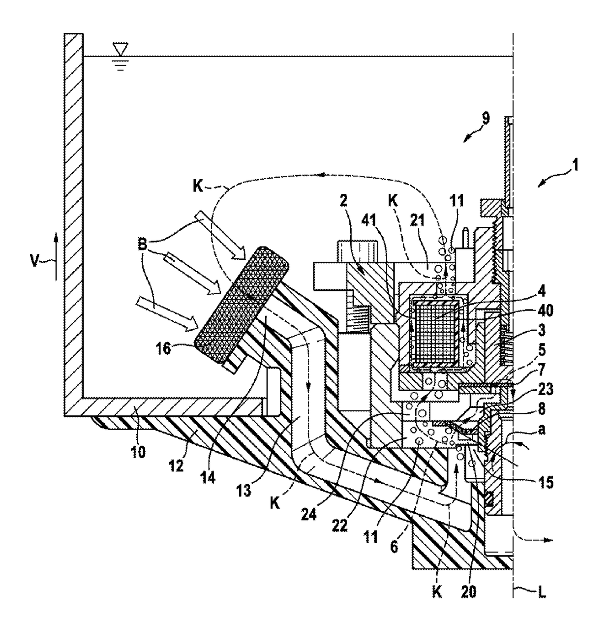
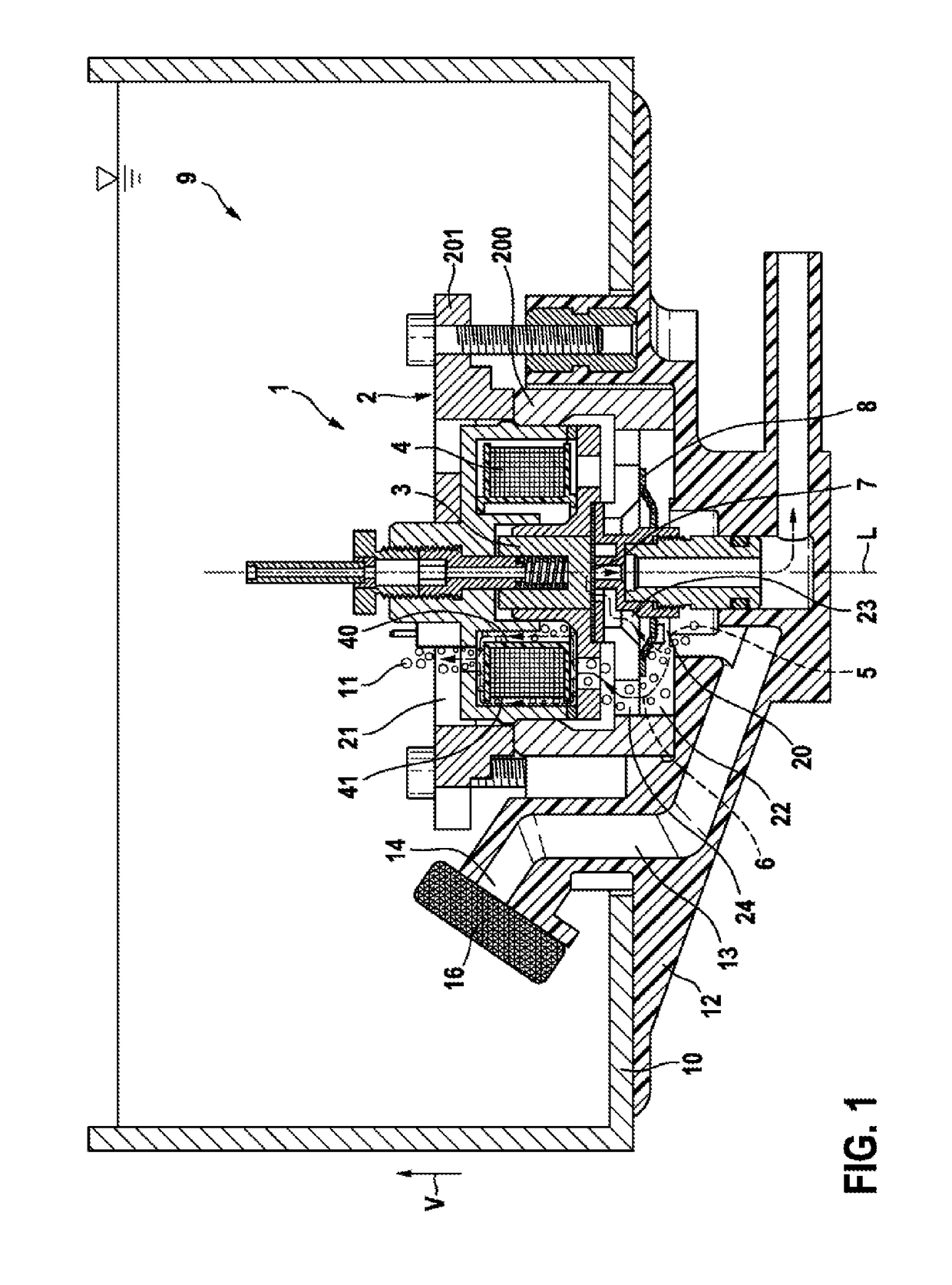
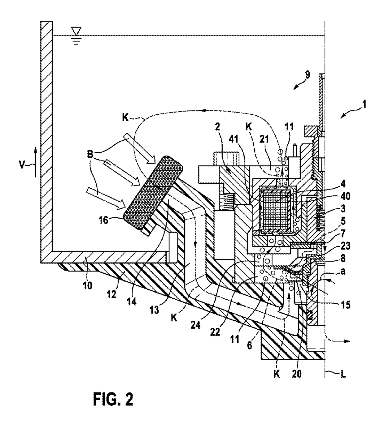
[0032]With reference to FIGS. 1 and 2, a fuel pump 1 and fuel pump arrangement 9 according to a first exemplary embodiment of the present invention are described in detail below.

[0033]As evident from FIGS. 1 and 2, the fuel pump 1 according to the invention is partially arranged in a fuel tank 10 of the fuel pump arrangement 9.

[0034]Furthermore, the fuel pump 1 comprises a pump housing 2, a delivery element 3 for delivering fuel, and a heat-generating actuator 4 formed as a magnetic coil for actuating the delivery element 3. The delivery element 3 is formed as a piston. Furthermore, the fuel pump 1 has a first fuel path 5 which leads from an inlet 20 to a delivery space 7, and a second fuel path 6 which leads from the inlet 20 past the heat-generating actuator 4 to a first housing opening 21.

[0035]According to the invention, the first housing opening 21 is arranged above the inlet 20 in a vertical direction V. In operation of the fuel pump 1, this arrangement causes a stack effect w...


PUM


Abstract

The present invention relates to a fuel pump (1) which comprises a pump housing (2), a delivery element (3) for delivering fuel, a heat-generating actuator (4) for actuating the delivery element (3), a first fuel path (5) which leads from an inlet (20) to a delivery space (7), and a second fuel path (6) which leads from the inlet (20) past the heat-generating actuator (4) to a first housing opening (21), wherein the first housing opening (21) is arranged above the inlet (20) in the vertical direction (V). The present invention also relates to a fuel pump arrangement which comprises a fuel pump (1) according to the invention and a fuel tank (10) in which the fuel pump (1) is at least partially and preferably entirely arranged. The present invention also relates to a method for operating a fuel pump (1).

Description

BACKGROUND OF THE INVENTION[0001]The present invention concerns a fuel pump for supplying fuel in a motor vehicle, such as e.g. a motorcycle. A further aspect of the present invention concerns a fuel pump arrangement which comprises such a fuel pump and a fuel tank in which the fuel pump is arranged. Furthermore, the present invention concerns a method for operating such a fuel pump.[0002]Such a fuel pump is known for example from GB 2478876 B. This is a fuel pump, in particular a magnetic piston pump, which has a piston, an actuator for operating the piston, a return element for returning the piston to a starting position, an inlet valve, a delivery space and an outlet valve. By actuation of the piston, in the intake phase fuel is drawn into the delivery space via the inlet valve. In the delivery phase, the fuel is conveyed from the delivery space via the outlet valve. Under temperature loading and at low suction pressure, the fuel can gasify at the inlet valve, whereby the deliver...

Claims


Application Information

Patent Timeline
IPC IPC(8): F02M37/04F02B61/02F02M37/00F02M31/18F04F1/18F02M37/10F02M31/125
CPCF02M37/043F02M37/103F02B61/02F02M37/0052F02M31/18F04F1/18F02M31/125F04B15/06F04B15/08Y02T10/12F02M37/08F02M37/10F02M37/106F02M51/04F02M57/027F04B17/04F04B17/044F04B17/046F04B17/048F04B35/045
Inventor PLISCH, ANDREASNITSCHE, FRANKHEYSE, JOERGFLO, SIAMENDALLGEIER, THORSTENMAEURER, WALTERREULE, TIM
Owner ROBERT BOSCH GMBH
Why Eureka
Try Eureka