
Residence structures and related methods

a technology of residence structure and structure, applied in the field of residence structure, can solve the problems of inconvenient dosing regimen, poor adherence rate of patients to self-administration protocol for therapeutics and diagnostics over an extended or indefinite period, and the greatest challenge of low adherence ra

Inactive Publication Date: 2017-09-21
MASSACHUSETTS INST OF TECH +1
View PDF3 Cites 22 Cited by
  • Summary
  • Abstract
  • Description
  • Claims
  • Application Information

AI Technical Summary

Benefits of technology

The patent text describes how exposure to certain substances can cause the dissociation of enteric elastomer linkers, which can help to break down the structure of the retention structure and allow it to pass through the internal orifice. This can have technical effects on the performance of the retention structure.

Problems solved by technology

The technical problem addressed in this patent text is the low adherence rates of patients to self-administration protocols for therapeutics and diagnostics, particularly for chronic asymptomatic conditions where the therapy has no immediate tangible benefit. The challenge of low adherence rates is greatest in primary and secondary prevention applications where the therapy has no immediate tangible benefit. The current state-of-the-art approaches to improving adherence rates include educational interventions, telephone-based counseling, health information technology solutions, interactive pharmacy tools, and changing models of payment for care. However, these approaches have only achieved modest improvements. The challenge of delivering therapeutic agents with high potency is that oral delivery systems have a short transit time through the gastrointestinal tract, making it difficult to achieve extended release beyond 24 hours via the oral route. The patent text proposes a solution to this problem by prolonging the transit time of an orally-administered therapeutic and addressing the challenges of gastric residence for drug delivery.

Method used


Image

  • Residence structures and related methods
  • Residence structures and related methods
  • Residence structures and related methods

Examples


example 1

l Ring Design

[0337]Polycaprolactone (PCL) was chosen as the loadable polymeric component of the structures due to its mechanical and physicochemical properties, unless otherwise stated. PCL is a degradable polyester with a low melting point of around 60° C. allowing multiple processing technologies. It is slowly degraded by hydrolysis of its ester linkages in physiological conditions, making it an appropriate material for the preparation of certain embodiments of long-term in vivo residence structures. It has been used for controlled release and targeted delivery of a variety of drugs.

[0338]Various flexible materials were tested for use as a flexible linker. Properties assessed included the ability to undergo 180-degree deformation without breaking, ability to remain in the deformed state for a prolonged period of time such as would occur in a stored pill, and ability to recoil nearly 100% to the original shape. To maximize the mechanical properties while maintaining biocompatibilit...

example 2

ed Star Design

[0341]Design constraints were addressed by using a combination of relatively rigid elements (loadable polymeric components) as drug matrix that provide mechanical stability and flexible recoil elements (elastic polymeric components.) As shown in FIGS. 4A-5B, two geometric families of rigid and flexible elements were studied in greater detail, a “polygon” family of alternating rigid and flexible elements which fold on itself and a “stellate” family in which rigid elements project from a central flexible element. Designs which could be efficiently encapsulated into a standard size 000 gelatin capsule were generated in Inventor CAD software, 3D printed, and used as positives to make PDMS negative molds. Versions optimized for capsules of other sizes, including larger veterinary capsules, as well as smaller capsules for more ready human consumption including 00-EL, 0-EL were also developed.

[0342]In FIG. 4A, the structure comprises a central core and six radial projections,...

example 3

Design

[0344]In FIG. 5A, an embodiment with a hexagonal structure is shown next to a 000-size capsule. The vertices of the hexagon comprise elastic polymeric components, and the sides of the hexagon comprise rigid loadable polymeric components. Each side has a length equal to just less than the length of the capsule such that the unencapsulated final form has a circumscribing diameter equal to nearly twice the capsule length. FIG. 5B, various structures with radial projections having sector shapes with internal sector angles equal to approximately 360° / N are illustrated. Four embodiments with square, hexagonal, octahedral, and dodecahedral structures, respectively, are shown in their unencapsulated forms. The shapes are formed from at least one material with a high elastic modulus to increase the resistance to compression and duration of gastric residence.

[0345]Each side of each polygon is about 22-mm long, and each folded polygonal structure has a width of about 8.5 mm. For a struct...


PUM

PropertyMeasurementUnit
Lengthaaaaaaaaaa
Fractionaaaaaaaaaa
Timeaaaaaaaaaa

Abstract

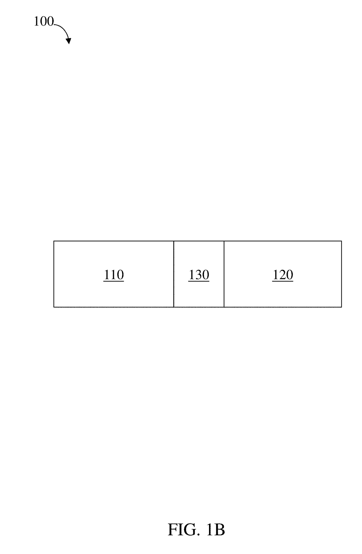
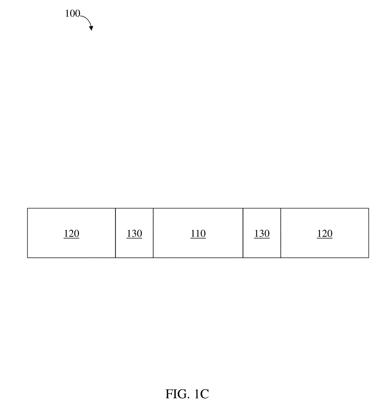
Residence structures, systems, and related methods are generally provided. Certain embodiments comprise administering (e.g., orally) a residence structure to a subject (e.g., a patient) such that the residence structure is retained at a location internal to the subject for a particular amount of time (e.g., at least about 24 hours) before being released. The residence structure may be, in some cases, a gastric residence structure. In some embodiments, the structures and systems described herein comprise one or more materials configured for high levels of active substances (e.g., a therapeutic agent) loading, high active substance and/or structure stability in acidic environments, mechanical flexibility and strength in an internal orifice (e.g., gastric cavity), easy passage through the GI tract until delivery to at a desired internal orifice (e.g., gastric cavity), and/or rapid dissolution/degradation in a physiological environment (e.g., intestinal environment) and/or in response to a chemical stimulant (e.g., ingestion of a solution that induces rapid dissolution/degradation). In certain embodiments, the structure has a modular design, combining a material configured for controlled release of therapeutic, diagnostic, and/or enhancement agents with a structural material necessary for gastric residence but configured for controlled and/or tunable degradation/dissolution to determine the time at which retention shape integrity is lost and the structure passes out of the gastric cavity. For example, in certain embodiments, the residence structure comprises a first elastic component, a second component configured to release an active substance (e.g., a therapeutic agent), and, optionally, a linker. In some such embodiments, the linker may be configured to degrade such that the residence structure breaks apart and is released from the location internally of the subject after a predetermined amount of time.

Description


Claims


Application Information

Patent Timeline
Owner MASSACHUSETTS INST OF TECH
Learn More