Temperature control system for hybrid powertrain and method of operating a temperature control system

a technology of temperature control system and hybrid powertrain, which is applied in the direction of liquid cooling, engine cooling apparatus, machines/engines, etc., can solve the problem of high energy consumption

Active Publication Date: 2017-09-14
AUDI AG
View PDF11 Cites 4 Cited by
  • Summary
  • Abstract
  • Description
  • Claims
  • Application Information

AI Technical Summary

Benefits of technology

The present invention provides a cooling system for electronic devices that allows for efficient cooling and temperature control. The invention includes two subcircuits that can be connected or disconnected through a valve device, which allows for fluid communication with different cooling devices. This allows the system to cool the first drive device when its temperature is lower than its operating temperature, using heat produced by the second drive device. The coolant duct is also associated with the second operating mode to prevent coolant from flowing through the cooling device. The technology achieves efficient cooling and temperature control for electronic devices.

Problems solved by technology

This is accompanied by high energy consumption.

Method used


Image

  • Temperature control system for hybrid powertrain and method of operating a temperature control system
  • Temperature control system for hybrid powertrain and method of operating a temperature control system

Examples


Embodiment Construction

[0030]The depicted embodiment is to be understood as illustrative of the invention and not as limiting in any way. It should also be understood that the FIGURE may not necessarily be to scale. In certain instances, details which are not necessary for an understanding of the present invention or which render other details difficult to perceive may have been omitted.

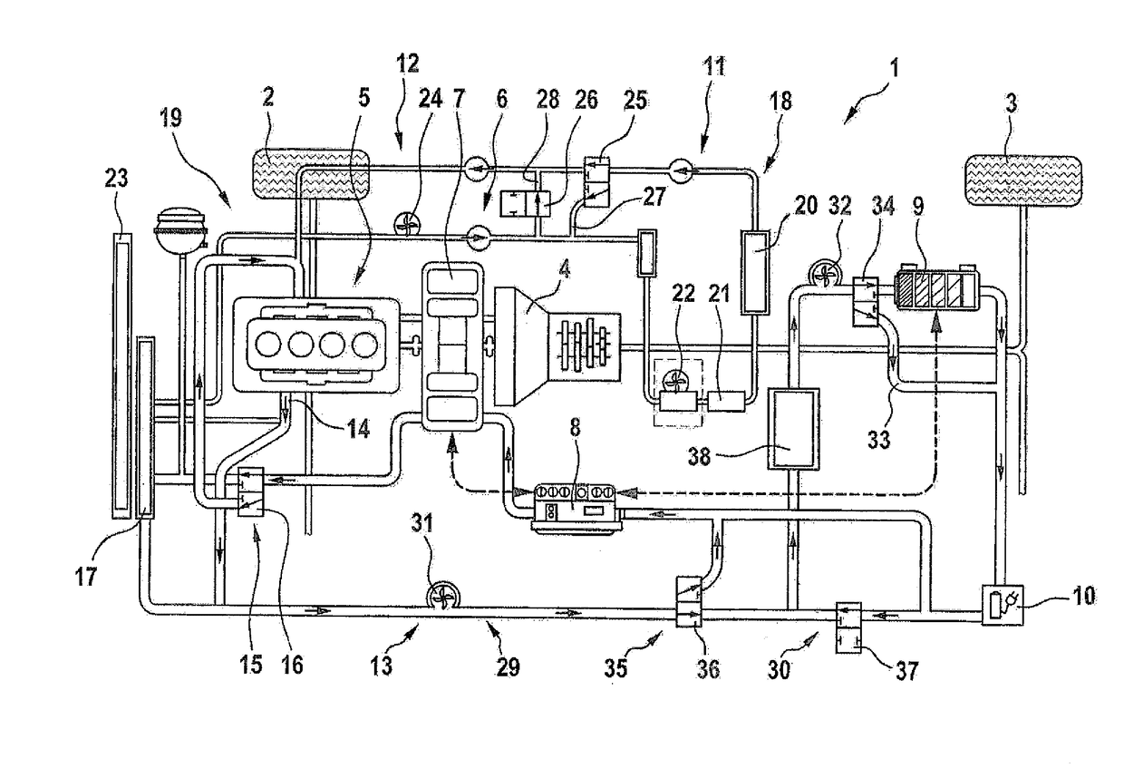
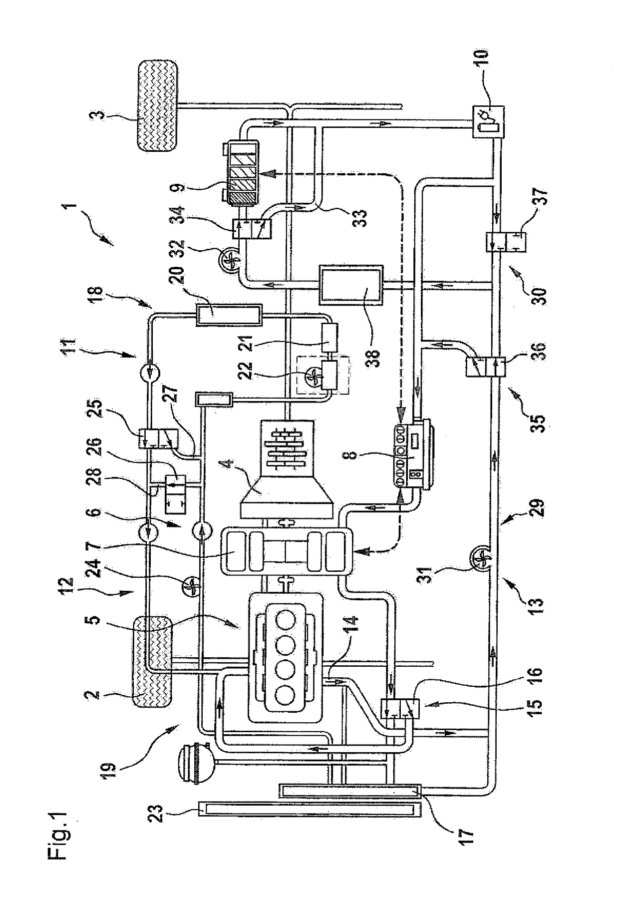
[0031]Turning now to FIG. 1, there is shown a schematic illustration of a hybrid powertrain in accordance with the present invention, generally designated by reference numeral 1, for powering a motor vehicle which is represented in FIG. 1 solely by the depiction of a wheel 2 of a front axle and a wheel 3 of the rear axle. At least the wheel 3 can be powered by the hybrid powertrain 1. The hybrid powertrain 1 includes a transmission 4, e.g. a multi-speed transmission, via which the wheel 3 is operably connected to a first drive device 5 and a second drive device 6. The first drive device 5 is an internal combustion engine, ...


PUM


Abstract

A temperature control system for a hybrid powertrain includes a first coolant circuit for temperature control of a first drive device of the hybrid powertrain and a second coolant circuit for temperature control of a second drive device. The second coolant circuit has a first subcircuit, connected for heat transfer to the second drive device, and a second subcircuit, connected at least temporarily for heat transfer to an energy store of the second drive device. The first and second subcircuits are operable separately from one another. A coolant duct is connected to the first drive device for heat transfer and is fluidly connected in a first operating mode with the first coolant circuit in the absence of a fluid communication with the second coolant circuit, and fluidly connected in a second operating mode with the second coolant circuit in the absence of a fluid communication with the first coolant circuit.

Description

CROSS-REFERENCES TO RELATED APPLICATIONS[0001]This application claims the priority of German Patent Application, Serial No. 10 2016 008 076.3, filed Mar. 12, 2016, pursuant to 35 U.S.C. 119(a)-(d), the disclosure of which is incorporated herein by reference in its entirety as if fully set forth herein.BACKGROUND OF THE INVENTION[0002]The present invention relates to a temperature control system for a hybrid powertrain and method of operating a temperature control system[0003]The following discussion of related art is provided to assist the reader in understanding the advantages of the invention, and is not to be construed as an admission that this related art is prior art to this invention.[0004]A hybrid powertrain is used for example to power a motor vehicle by using different types of drive devices to produce the necessary torque. One drive device may be an internal combustion engine and another drive device may be an electric machine. During operation, the first and second drive ...

Claims


Application Information

Patent Timeline
Patent Type & Authority Applications(United States)
IPC IPC(8): F01P3/20F01P9/06F01P7/16
CPCF01P3/20F01P2050/24F01P9/06F01P7/165
Inventor AUERBACH, MICHAELBRUNNER, JOHANNESKLEISCH, RALFOBERTING, ANDREAS
Owner AUDI AG
Why Eureka
Try Eureka