
Vacuum gauge and contamination diagnosis method

Inactive Publication Date: 2017-09-07
NAT INST OF ADVANCED IND SCI & TECH
View PDF5 Cites 0 Cited by
  • Summary
  • Abstract
  • Description
  • Claims
  • Application Information

AI Technical Summary

Benefits of technology

The present invention provides a vacuum gauge that can accurately diagnose its level of contamination using a simple device. This makes it easy to maintain the vacuum gauge and ensures that it is always functioning properly. The diagnosis method is also straightforward, making it easy to detect any contamination.

Problems solved by technology

For example, in a semiconductor manufacturing apparatus, a pressure within a chamber is measured by using a vacuum gauge, and it is, however, known that performance of an ionization vacuum gauge is deteriorated when used in a contaminated environment.
Supposing that the ionization vacuum gauge does not indicate a normal value due to the deterioration, it follows that a large quantity of defective products are produced due to a progress of a semiconductor process under an abnormal condition.
At this time, especially in the case of a fault mode in which the value displayed on the ionization vacuum gauge slightly deviates from the normal value, there arises a problem of not being aware of a fault in many cases.
Herein, there has hitherto been generally adopted a method of checking soundness of the vacuum gauge by calibrating the vacuum gauge through a test or an examination after removing the vacuum gauge from the semiconductor manufacturing apparatus, and this method has, however, a problem that an operating ratio of the semiconductor manufacturing apparatus drops down because of requiring a considerable length of time and a considerable cost.
A method of making the calibration by introducing a testing gas into a vacuum apparatus does not spread due to an anxiety for contaminating the vacuum apparatus, and due to involving a labor and a cost as well.

Method used


Image

  • Vacuum gauge and contamination diagnosis method
  • Vacuum gauge and contamination diagnosis method
  • Vacuum gauge and contamination diagnosis method

Examples


Embodiment Construction

[0023]An embodiment of the present invention will hereinafter be described in detail with reference to the drawings. Note that the same reference numerals and symbols represent the same or corresponding components in the drawings throughout.

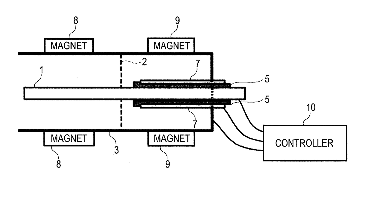
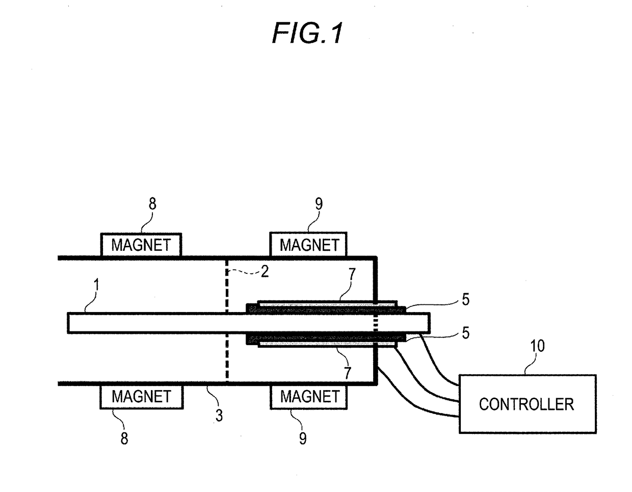
[0024]FIG. 1 is a diagram illustrating a configuration of a cold cathode ionization vacuum gauge according to the embodiment of the present invention. As illustrated in FIG. 1, the cold cathode ionization vacuum gauge according to the embodiment of the present invention includes an anode 1, a partition plate 2, a cathode 3, insulators 5, 5, anodes 7, 7, magnets 8, 9, and a controller 10. Herein, the anode 1 and the anode 7 are disposed in a face-to-face relationship with the cathode 3, in which the cathode 3 disposed in the face-to-face relationship with the two anodes 1 and 7 is configured as a common electrode having a same electric potential.

[0025]The two anodes 7, 7 and the anode 1 are electrically insulated from each other by the insulators ...


PUM


Abstract

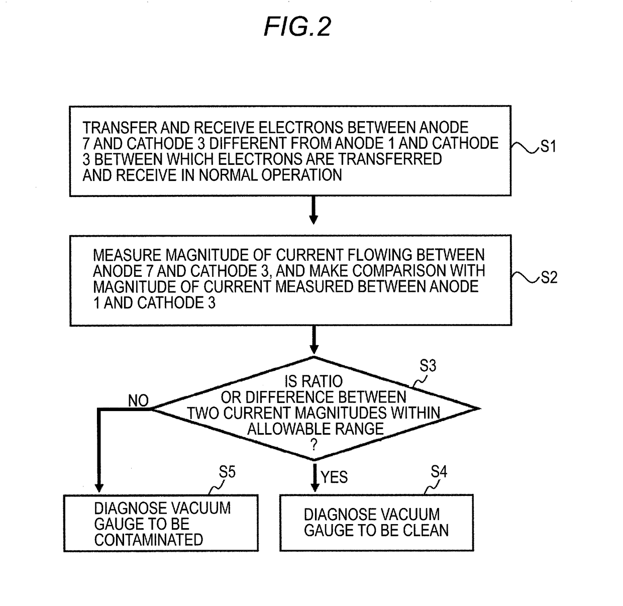
Provided are: a vacuum gauge that, with a simple configuration, can accurately diagnose the degree of contamination of the vacuum gauge; and a contamination diagnosis method that, with a simple process, can accurately diagnose the degree of contamination of a vacuum gauge. Provided is a cold cathode ionization vacuum gauge that has a normal operation mode and a contamination diagnosis mode, the cold cathode ionization vacuum gauge comprising: an anode 1 and a cathode 3 that are for measuring vacuum pressure in the normal operation mode; an anode 7 and the cathode 3 that are for measuring the vacuum pressure in the contamination diagnosis mode; and a controller 10 that compares the size of a current measured between the anode 7 and the cathode 3 and the size of a current measured between the anode 1 and the cathode 3.

Description

TECHNICAL FIELD[0001]The present invention pertains to a vacuum gauge, and a method of diagnosing a contamination level of the vacuum gauge.BACKGROUND ART[0002]For example, in a semiconductor manufacturing apparatus, a pressure within a chamber is measured by using a vacuum gauge, and it is, however, known that performance of an ionization vacuum gauge is deteriorated when used in a contaminated environment.[0003]Supposing that the ionization vacuum gauge does not indicate a normal value due to the deterioration, it follows that a large quantity of defective products are produced due to a progress of a semiconductor process under an abnormal condition. At this time, especially in the case of a fault mode in which the value displayed on the ionization vacuum gauge slightly deviates from the normal value, there arises a problem of not being aware of a fault in many cases.Therefore, a determination of the deterioration has been tried to be made by some methods. Herein, there has hither...

Claims


Application Information

Patent Timeline
IPC IPC(8): G01L27/00G01L21/34
CPCG01L21/34G01L27/00G01L21/32G01L27/007G01N27/62H01J27/02H01J37/08H01J41/06
Inventor YOSHIDA, HAJIME
Owner NAT INST OF ADVANCED IND SCI & TECH
Learn More