Method and system for designing a stair lift rail assembly

a technology for stair lifts and rail assemblies, applied in the field of stairs, can solve the problems of high cost, prone to errors, and consume relatively much time, and achieve the effect of reducing the time to measur

Inactive Publication Date: 2017-08-24
HANDICARE STAIRELEVATORS
View PDF4 Cites 14 Cited by
  • Summary
  • Abstract
  • Description
  • Claims
  • Application Information

AI Technical Summary

Benefits of technology

[0007]It would be desirable to provide an alternative to the use of markers to acquire an accurate three-dimensional representation of the staircase and its environment. It would also be desirable to decrease the time to measure an actual staircase.
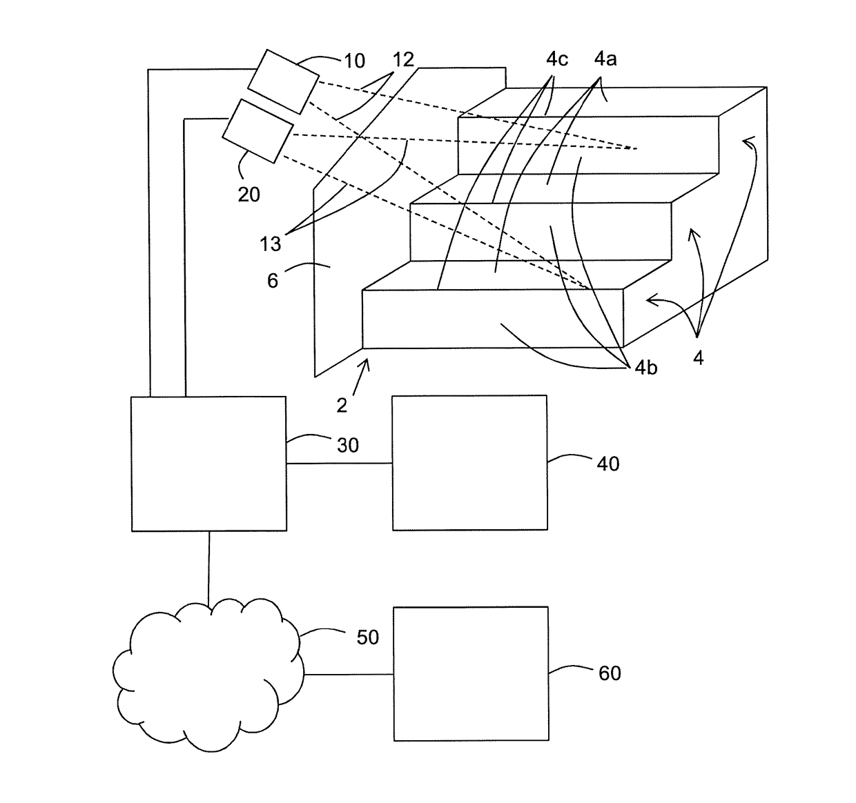
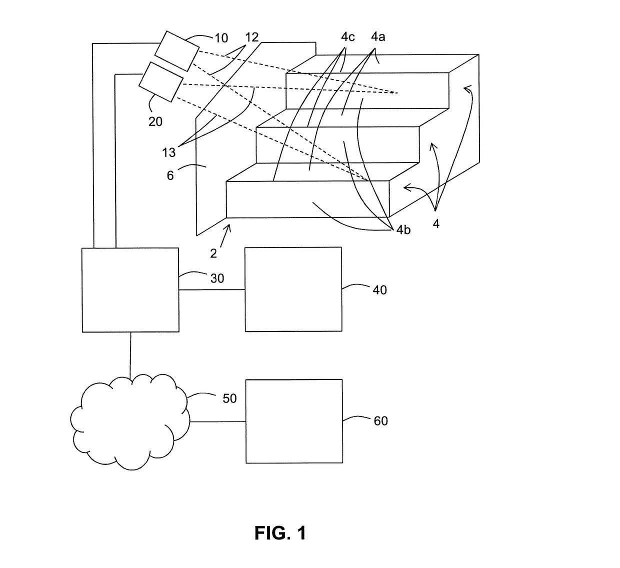
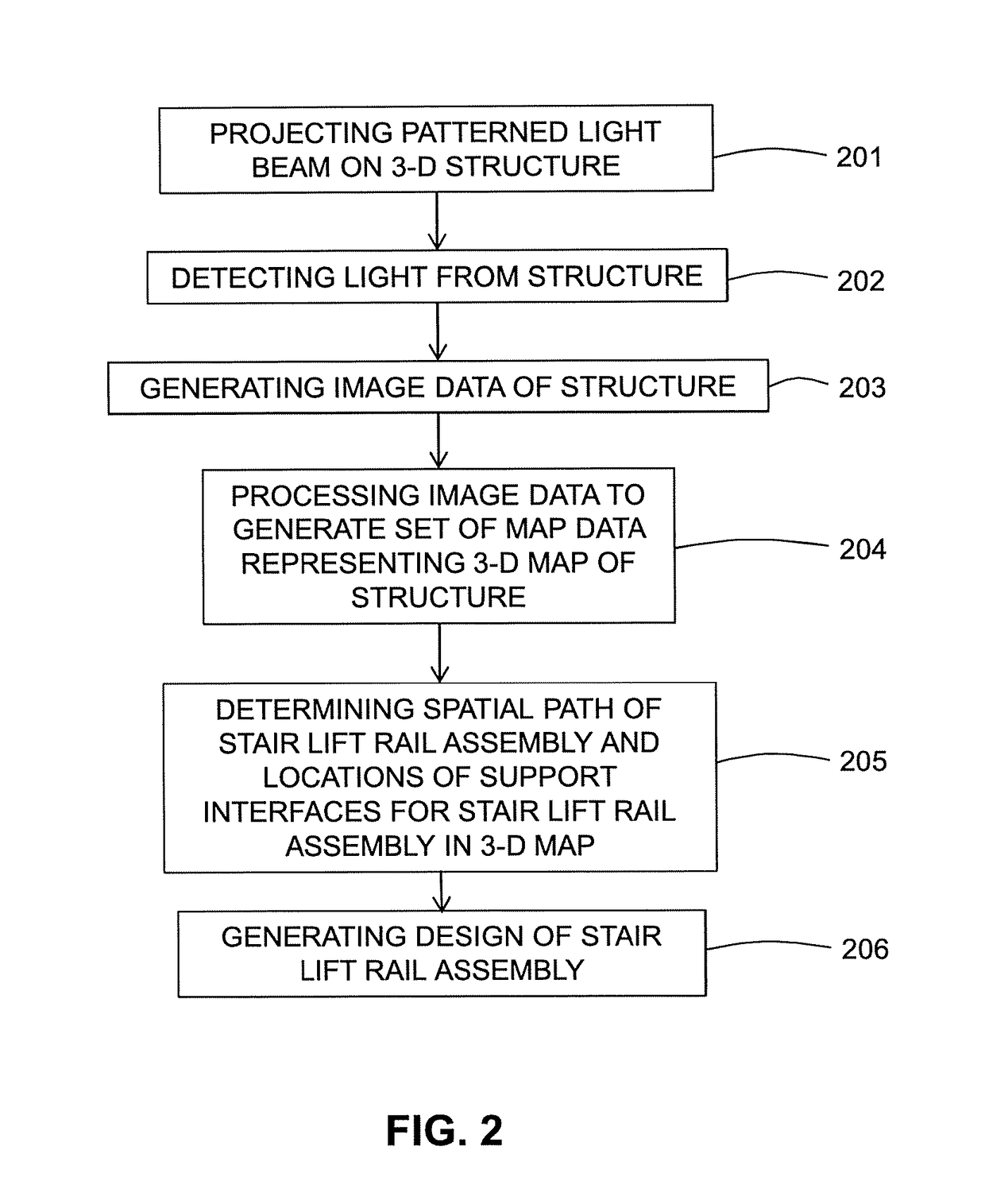
[0015]In the method of the invention, the use of markers can be prevented or omitted. Rather, an optically patterned light beam is used to extract depth information from a three-dimensional structure, which depth information includes a distance between the reference location and a part of the structure. The depth information allows to create a set of map data representing a three-dimensional map of said part of the structure.
[0020]In practice, a three-dimensional structure may have dimensions in one or more directions, or shapes, that are such as to prevent the structure from being captured as a whole by projecting a light beam towards it. For example, the transverse extension of the light beam allows projecting it only on part of a three-dimensional structure. As another example, the light beam could be projected on the whole of the three-dimensional structure, but this would require such a large distance between the reference location and the structure that an accuracy of image data and / or map data would be unacceptably low. As still another example, the structure can have different parts that are only visible from different reference locations. In all of these and other cases, it is necessary to generate different sets of map data for different (surface) parts of the structure. The different sets of map data may be produced using the same reference location, or they may be produced using different reference locations. By data-stitching or correlating the different sets of map data with each other, an extended set of map data is provided. The extended set of map data represents a three-dimensional map of a combination of the different parts of the structure. The different (surface) parts of the structure may partly overlap, thereby facilitating the correlation process.
[0030]The set of map data comprises quantization errors, which may complicate an identification of steps of the stairs and / or a wall adjacent to the stairs and / or a railing structure adjacent to the stairs, and which may complicate determining a location of a support interface. Quantization errors, which may be due to the digitalization processes used in the method and system of the present invention, induce local variations in surface and line properties in the three-dimensional map, showing them to be irregular while in reality such surfaces and lines are flat and straight, respectively. To alleviate this problem, in some embodiments of the method, the step of identifying a series of steps comprises determining a plurality of points associated with a top face of the step in the set of map data, fitting a top plane to the plurality of points associated with the top face, and redefining the top plane as the top face in the set of map data. In some embodiments of the method, the step of identifying a series of steps comprises determining a plurality of points associated with the front face of the step in the set of map data, fitting a front plane to the plurality of points associated with the front face, and redefining the front plane as the front face in the set of map data. In some embodiments of the method, the step of identifying a series of steps comprises determining a plurality of points associated with the nose of the step in the set of map data, fitting a nose line to the plurality of points associated with the nose, and redefining the nose line as the nose in the set of map data. In some embodiments of the method, the step of identifying a wall, floor or ceiling adjacent to the stairs comprises determining a plurality of points associated with the wall, floor or ceiling in the set of map data, fitting one or more geometrical surfaces to the plurality of points associated with the wall, floor or ceiling, and redefining the one or more geometrical surfaces as the wall, floor or ceiling in the set of map data. In some embodiments of the method, the step of identifying a railing structure adjacent to the stairs comprises determining a plurality of points associated with the railing structure in the set of map data, fitting one or more geometrical surfaces to the plurality of points associated with the railing structure, and redefining the one or more geometrical surfaces as the railing structure in the set of map data. In such enhanced set of map data, an accuracy of locating support interfaces on the three-dimensional structure is improved by inclusion of the top plane, the front plane, the nose line, and the one or more geometrical surfaces, respectively.

Problems solved by technology

Although in the process of designing and producing a stair lift several efficiency enhancing steps have been developed over time, the first step of measuring an actual staircase using markers disadvantageously consumes relatively much time, and thus induces relatively high costs.
Since this positioning is a process performed by a person, it is prone to errors, such as mislaying specific markers, or omitting relevant markers.
Further disadvantages of the use of optical markers are that they may become soiled, damaged or lost, rendering a set of markers unfit for use.
This may lead to incomplete measurements, or postponement of measurement, awaiting replacement markers.

Method used


Image

  • Method and system for designing a stair lift rail assembly
  • Method and system for designing a stair lift rail assembly
  • Method and system for designing a stair lift rail assembly

Examples


Embodiment Construction

[0042]FIG. 1 depicts a part of a staircase 2. The staircase comprises steps 4, each step having a top face 4a, a front face 4b, and a nose 4c. In FIG. 1, only three steps 4 are shown. However, the staircase 2 can have less than three, or more than three steps 4. The staircase 2 may slope up along a straight line, as indicated in FIG. 1. However, the staircase 2 may also slope up along a curved line. Different steps 4 may have equal or different widths and / or heights. Top faces 4a and / or front faces 4b of different steps 4 can have a rectangular shape as shown in FIG. 1, or can have other shapes. In particular, a top face 4a can have a substantially trapezoidal shape, in particular when the width of consecutive steps 4 increases or decreases.

[0043]The staircase 2 may comprise a schematically indicated wall structure or railing structure 6 adjacent to the staircase 2. Other walls, floors, ceilings, and / or railing structures 6 may be present adjacent to the steps 4 of the staircase 2.

[...


PUM


Abstract

In a method and system of designing a stair lift rail assembly to be mounted on a three-dimensional structure, a light beam including an optical pattern on at least part of the structure is projected from a reference location relative to the structure. Light from the structure is detected. Image data of the structure are generated based on the detected light. The image data are processed to generate a set of map data of the structure, the set of map data representing a three-dimensional map of the structure. Spatial path of the stair lift rail and locations of support interfaces for the stair lift rail assembly in the three-dimensional map are determined. Design of the stair lift rail assembly is generated based on the spatial path of the stair lift rail and the locations of the support interfaces for the stair lift rail assembly.

Description

CROSS-REFERENCE TO RELATED APPLICATIONS[0001]This application is the National Stage of International Application No. PCT / NL2015 / 050541 filed Jul. 23, 2015, which claims the benefit of Netherlands Application No. NL 2013355, filed Aug. 22, 2014, the contents of which is incorporated by reference herein.FIELD OF THE INVENTION[0002]The invention relates to the field of stair lifts, and more specifically to a method and system for designing a rail assembly of a stair lift, on which rail assembly a carrier can be moved to convey a person along a staircase.BACKGROUND OF THE INVENTION[0003]When a stair lift is to be designed for implementation at a particular staircase, a first step to take is to acquire an accurate three-dimensional representation of the staircase and its environment to identify interfaces on which to mount a guide, i.e. a rail assembly to support a movable carrier, of the stair lift. To acquire the three-dimensional representation of the staircase and its environment (fl...

Claims


Application Information

Patent Timeline
Patent Type & Authority Applications(United States)
IPC IPC(8): G06T7/521B66B9/08G06T7/60G01B11/25G06F17/50
CPCG06T7/521G01B11/25G06T2207/10028G06T7/60B66B9/0846G06F17/5009E04F21/26G01B11/00B66B9/08G06F30/20
Inventor NUIJTEN, JOHANNES MARIA ANTONIUS
Owner HANDICARE STAIRELEVATORS
Why Eureka
Try Eureka