
Generation and encoding of residual integral images

a residual integral and image technology, applied in the field of image processing, can solve the problems of large increase in the size of the integral image constructed in this way, difficulty in the practical implementation of integral imaging systems, and high volume of information to be compressed, so as to optimize the signaling cost, optimize performance, and optimize the effect of coding cos

Active Publication Date: 2017-08-10
ORANGE SA (FR)
View PDF4 Cites 6 Cited by
  • Summary
  • Abstract
  • Description
  • Claims
  • Application Information

AI Technical Summary

Benefits of technology

The patent text describes a coding method for 3D images that allows for efficient compression of angular information while retaining high resolution. The method uses an integral image that is decomposed into multiple views, with each view then individually coded. This allows for a smaller amount of data to be used for coding, reducing costs. Additionally, the method includes a position parameter that indicates the position of the view during coding and decoding. This parameter helps to optimize signaling costs and reduce the amount of data needed to store the image. Overall, the method prioritizes quality and reduces costs for 3D image compression.

Problems solved by technology

Despite the attractions of a technique of this kind, there are difficulties in the practical implementation of integral imaging systems.
This results in much too large an increase in the size of the integral image constructed in this way.
Thus if the integral image must be coded, there is a high volume of information to be compressed and performance in terms of compression of the integral image is poor.
The major drawback of a first method of the above kind lies in the fact that, the resolution of the integral image being very high, it is difficult to code.
This first method obliges compression of a high volume of information, which results in poor performance.
A drawback of this second coding method is that its practical application imposes a limitation on the number of views to be coded by the MVC technique.

Method used


Image

  • Generation and encoding of residual integral images
  • Generation and encoding of residual integral images
  • Generation and encoding of residual integral images

Examples


Embodiment Construction

of the Decoding Part

[0245]One embodiment of the decoding method according to the invention will now be described in which the decoding method is implemented in software or hardware by modification of a decoder initially conforming to any current or future video decoding standards.

[0246]The decoding method according to the invention is represented in the form of an algorithm including steps D1 to D5 as represented in FIG. 6. As shown in FIG. 5, the decoder DO according to this embodiment of the invention includes a memory MEM_DO including a buffer memory TAMP_DO, a processor unit UT_DO including for example a microprocessor μP and controlled by a computer program PG_DO that implements the decoding method according to the invention. At the time of initialization, the code instructions of the computer program PG_DO are for example loaded into a RAM before being executed by the processor of the processor unit UT_DO.

[0247]The decoding method represented in FIG. 6 is applied to any curren...


PUM


Abstract

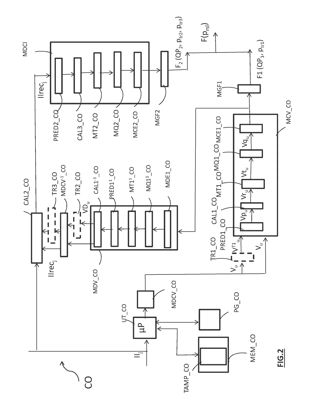
The invention concerns the encoding of at least one current integral image (IIj) captured by an image capture device, comprising the steps consisting of: —decomposing (C1) the current integral image into at least one frame (Vu) representing a given perspective of a scene and, from at least one image capturing parameter associated with the image capture device, —encoding (C2) said at least one frame, —decoding (C4) said at least one frame, —recomposing (C5) the current integral image from said at least one decoded frame by applying an inverse decomposition of said decomposition of the integral image and from said at least one image capturing parameter associated with the image capture device, said encoding method being characterised in that it implements the steps consisting of: —determining (C6) a residual integral image by comparing said at least one current integral image with said recomposed integral image, —encoding (C7) the data associated with the residual integral image and said at least one image capturing parameter associated with the image capture device.

Description

FIELD OF THE INVENTION[0001]The present invention relates generally to the field of image processing and more specifically to the coding and decoding of integral images and sequences of integral images.[0002]The invention may notably, although not exclusively, be applied to the video coding employed in present-day AVC and HEVC video coders and their extensions (MVC, 3D-AVC, MV-HEVC, 3D-HEVC, etc.) and to the corresponding video decoding.PRIOR ART[0003]Integral imaging is a technique that consists in representing images in relief. It is considered particularly promising in the development of 3D television, notably because it proposes, rather than a stereoscopic visualization of the images, a total parallax.[0004]An integral image is conventionally composed of different elementary images also termed micro-images each of which represents a different perspective of a scene in three dimensions. An integral image is acquired by means of an image capture device that includes a video camera...

Claims


Application Information

Patent Timeline
Patent Type & Authority Applications(United States)
IPC IPC(8): H04N19/102H04N19/172H04N19/597H04N19/124
CPCH04N19/102H04N19/597H04N19/172H04N19/124H04N19/147
Inventor JUNG, JOELDRICOT, ANTOINE
Owner ORANGE SA (FR)
Learn More