
Bicycle hub apparatus

a technology of hub apparatus and bicycle, which is applied in the direction of mechanical actuator clutches, mechanical equipment, transportation and packaging, etc., can solve the problems of reducing the life time of the hub apparatus, increasing the damage of the driving teeth, and disadvantages of the conventional bicycle hub apparatus, so as to enhance the smoothness and firmness of engagement, accelerate the effect of speeding up the speed and enhancing the working depth

Inactive Publication Date: 2017-08-03
CHOSEN
View PDF0 Cites 3 Cited by
  • Summary
  • Abstract
  • Description
  • Claims
  • Application Information

AI Technical Summary

Benefits of technology

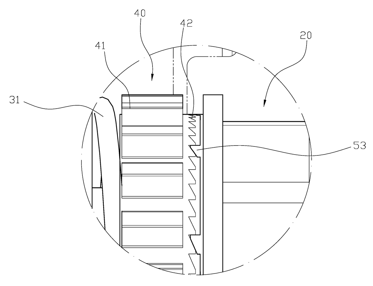
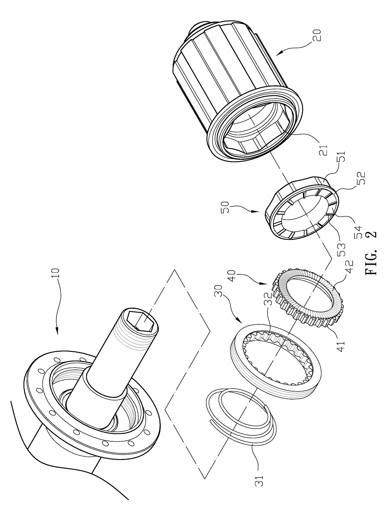
The present invention provides a bicycle hub apparatus that improves the smoothness and firmness of engagement between first and second engaging teeth. This is achieved by increasing the separation distance between adjacent second engaging teeth and the number of first engaging teeth. The second planes formed between adjacent second engaging teeth enhance the working depths between the two engaging teeth, improving the engagement between them. Compared to conventional bicycle hub apparatus, the present invention achieves a more rapid acceleration for the bicycle.

Problems solved by technology

However, the conventional bicycle hub apparatus is disadvantageous because: (i) the separated distances between each two teeth (821) and the number of the first driving teeth (821) on the first teeth base (82) of the first driving unit (80) are designed corresponding to the second driving teeth (941) on the second teeth base (94) of the second driving unit (90).
Thus, it might lead that the two driving teeth (821)(941) cannot firmly engage with each other, and the engagement between the first driving base (82) and the second driving base (94) becomes unreliable, resulting in increasing the damage of driving teeth and lowering the life time of the hub apparatus.

Method used


Image

  • Bicycle hub apparatus
  • Bicycle hub apparatus
  • Bicycle hub apparatus

Examples


Embodiment Construction

[0017]The detailed description set forth below is intended as a description of the presently exemplary device provided in accordance with aspects of the present invention and is not intended to represent the only forms in which the present invention may be prepared or utilized. It is to be understood, rather, that the same or equivalent functions and components may be accomplished by different embodiments that are also intended to be encompassed within the spirit and scope of the invention.

[0018]Unless defined otherwise, all technical and scientific terms used herein have the same meaning as commonly understood to one of ordinary skill in the art to which this invention belongs. Although any methods, devices and materials similar or equivalent to those described can be used in the practice or testing of the invention, the exemplary methods, devices and materials are now described.

[0019]All publications mentioned are incorporated by reference for the purpose of describing and disclos...


PUM


Abstract

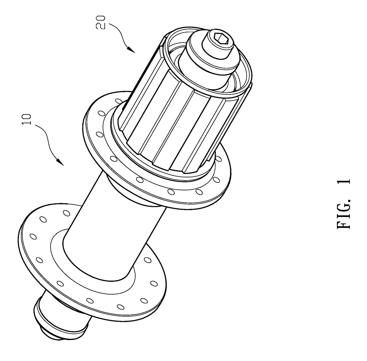
A bicycle hub apparatus may include a hub body and a freewheel body, and a first driving ring, a second driving ring, and third driving ring are sequentially located between the hub body and the freewheel body. The second driving ring is coupled inside the first driving ring to rotate around a shaft of the hub body simultaneously. A second lateral surface of the second driving ring facing to the third driving ring has a plurality of first engaging teeth, and a plurality of second engaging teeth protruding from a first surface of the third driving ring which faces to the second driving ring is configured to engage with the first engaging teeth of the second driving ring. The number of the second engaging teeth is a multiple of the first engaging teeth, to improve the engagement between the first engaging teeth and the second engaging teeth.

Description

FIELD OF THE INVENTION[0001]The present invention relates to a hub apparatus and more particularly to a bicycle hub apparatus.BACKGROUND OF THE INVENTION[0002]Generally, referring to FIGS. 9 to 11, a bicycle hub apparatus comprises a hub body (60) and a freewheel body (61), and a blocking ring (70) is formed inside an accommodating space of the hub body (60). An inner periphery of the blocking ring (70) has a plurality of tapered slots (71) arranged in a circular pattern, and a blocking edge (72) protrudes from an inner peripheral edge of the blocking ring (70). A first driving unit (80) formed between the hub body (60) and the freewheel body (61) comprises a first driving base (81). A plurality of first driving teeth (821) protruding from an outer surface of the first driving base (81) are arranged in a circular pattern. A second driving unit (90) located inside the blocking ring (70) can achieve axially linear movement relative to the tapered slots (71), and the second driving uni...

Claims


Application Information

Patent Timeline
Patent Type & Authority Applications(United States)
IPC IPC(8): B60B27/04F16D41/32B60B27/02
CPCB60B27/047B60B27/023F16D23/12B60B2900/212B60B2900/325F16D41/32F16D41/36B60B27/0031
Inventor CHEN, CHING-SHU
Owner CHOSEN
Learn More