Method, apparatus, and system for implementing packet loss detection

a packet loss detection and packet technology, applied in the field of communication technologies, can solve the problems of high packet loss rate, large impact on service, relatively high actual deployment cost, etc., and achieve the effect of high actual deployment cos

Inactive Publication Date: 2017-07-06
HUAWEI TECH CO LTD
View PDF0 Cites 2 Cited by
  • Summary
  • Abstract
  • Description
  • Claims
  • Application Information

AI Technical Summary

Benefits of technology

[0007]Embodiments of the present invention provide a method, an apparatus, and a system for implementing packet loss detection, which are used to resolve a prior-art problem of complex implementation and relatively high deployment costs.

Problems solved by technology

Particularly, in a high-throughput data center network, a high packet loss rate greatly affects a service.
Congestion is a main reason for packet loss, especially in such a scenario of the high-throughput data center network.
If packet loss detection is implemented by using this method, a detection function is required on each detected network element, causing relatively complex implementation and relatively high actual deployment costs.

Method used


Image

  • Method, apparatus, and system for implementing packet loss detection
  • Method, apparatus, and system for implementing packet loss detection
  • Method, apparatus, and system for implementing packet loss detection

Examples


first embodiment

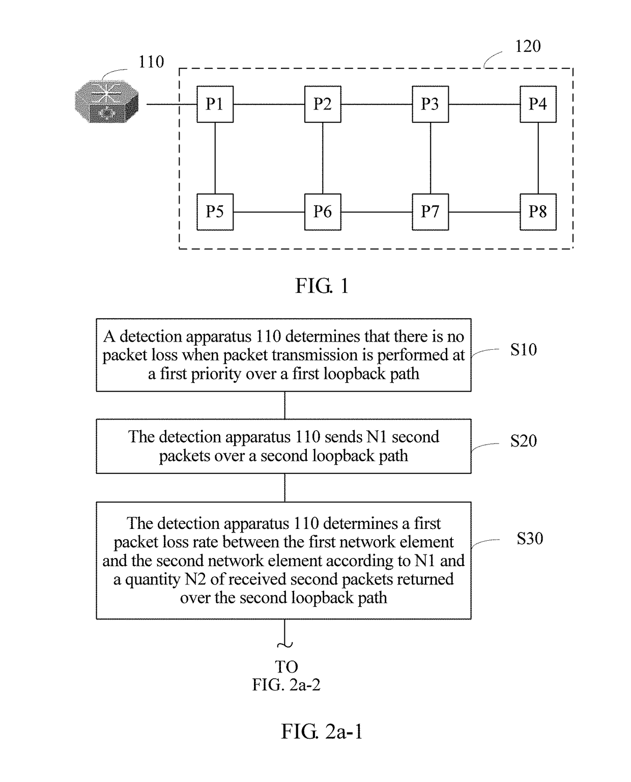
[0101]In conclusion, according to the method 100 in the present invention, a detection apparatus is connected to a network element in a communications network, and therefore, a packet loss rate between any two network elements (that is, a first network element and a second network element) in the communications network may be detected by performing steps S10 to S30, without a need to implement a detection function on a detected network element, thereby resolving a prior-art problem of relatively complex implementation and relatively high actual deployment costs.

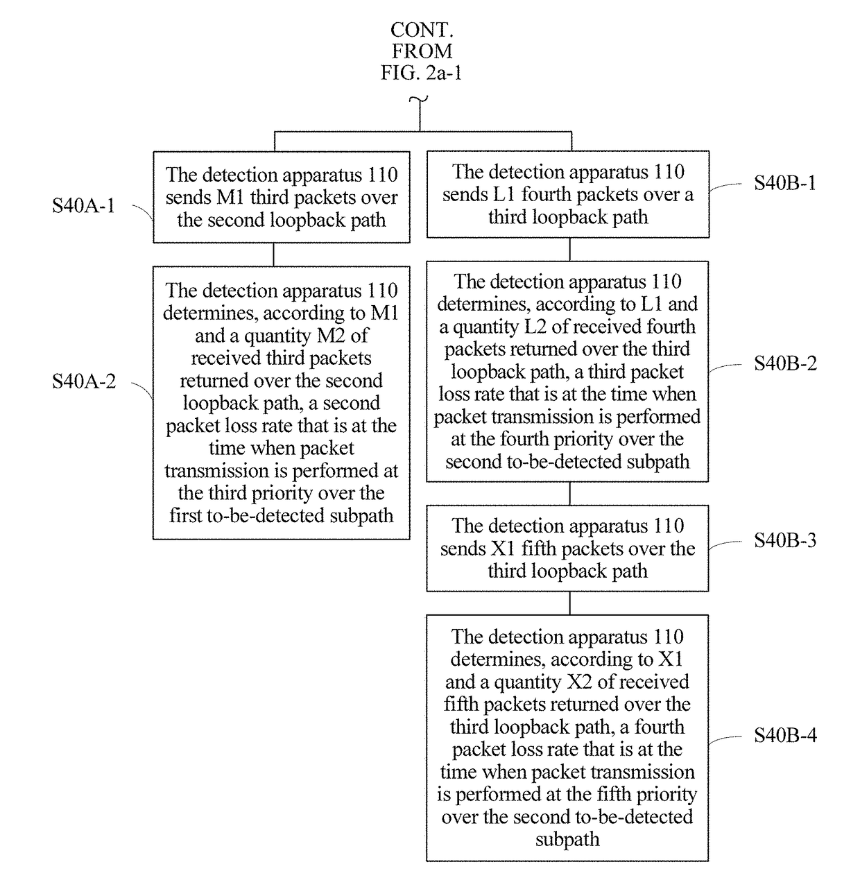
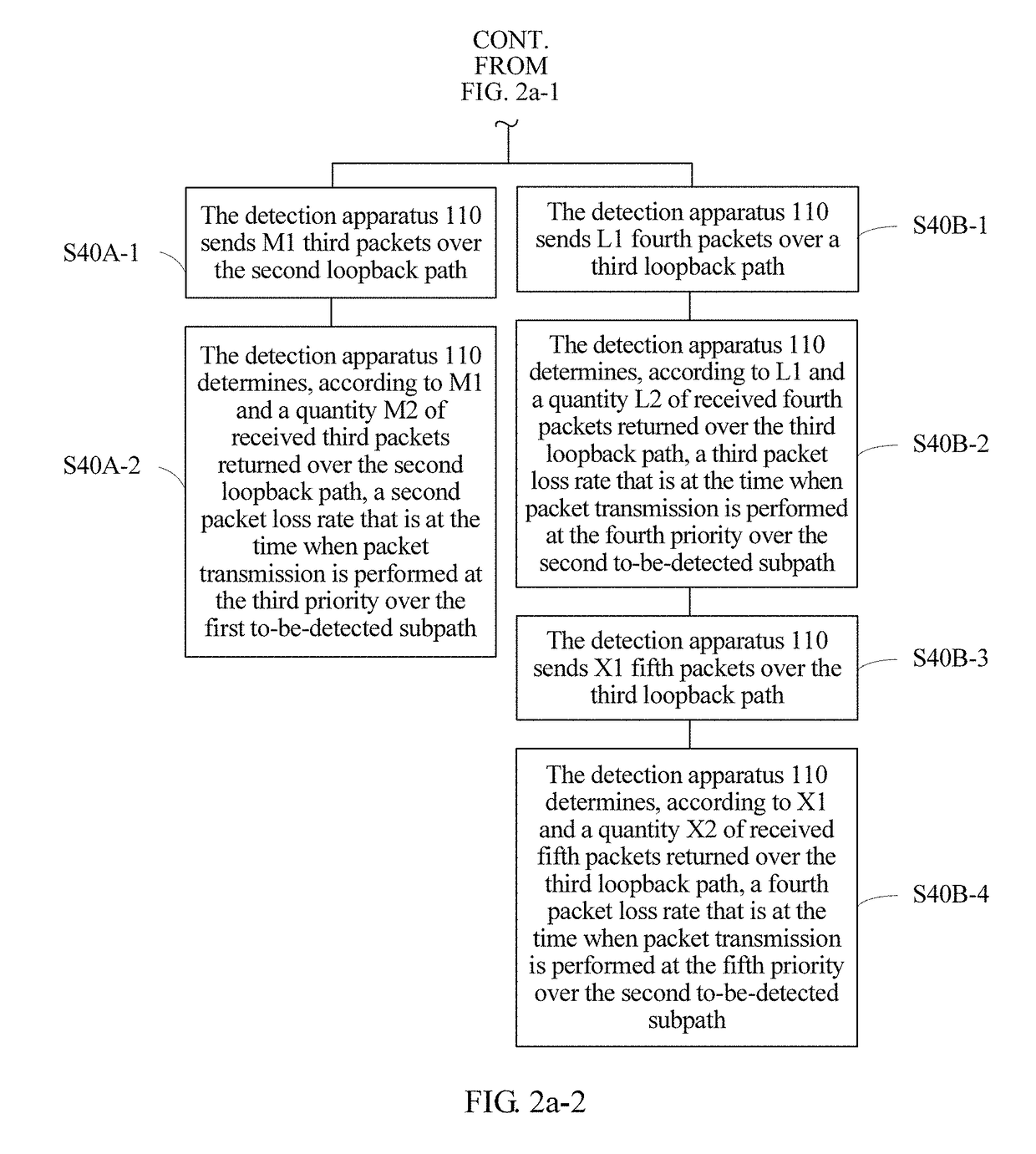
[0102]When the second priority is equal to the first priority, if the first packet loss rate detected by using steps S10 to S30 is 0 (that is, there is no fault-based packet loss), a congestion-based packet loss rate between the first network element and the second network element may be further detected by using steps S40A-1 and S40A-2.

[0103]S40A-1: The detection apparatus 110 sends M1 third packets over the second loopback ...

fifth embodiment

[0177]According to the detection system 2000 provided in the present invention, a packet loss rate between any two network elements (that is, a first network element 2021 and a second network element 2022) in a communications network 2020 can be detected only by implementing a detection function on a detection apparatus 2010, without a need to implement the detection function on a detected network element, thereby resolving a prior-art problem of relatively complex implementation and relatively high actual deployment costs because the detection function is required on each detected network element.

[0178]A person of ordinary skill in the art may be aware that, in combination with the examples described in the embodiments disclosed in this specification, units and algorithm steps may be implemented by electronic hardware or a combination of computer software and electronic hardware. Whether the functions are performed by hardware or software depends on particular applications and desi...


PUM


Abstract

A method, an apparatus, and a system for implementing packet loss detection. The method includes: determining, by a detection apparatus, there is no packet loss when packet transmission is performed at a first priority over a first loopback path that includes a first subpath and a second subpath; sending N1 packets over a second loopback path that includes the first subpath, the second subpath, a third subpath, and a fourth subpath, where the packets are transmitted at the first priority over the first subpath and the second subpath, and are transmitted at a second priority over the third subpath and the fourth subpath; and determining a packet loss rate according to N1 and a quantity N2 of received packets returned over the second loopback path. Therefore, a packet loss rate can be detected only by implementing a detection function on a detection apparatus, thereby resolving a problem of complex implementation.

Description

CROSS-REFERENCE TO RELATED APPLICATION[0001]This application claims priority to Chinese Patent Application No. 201511026130.3, filed on Dec. 30, 2015, which is hereby incorporated by reference in its entirety.TECHNICAL FIELD[0002]The present invention relates to the field of communications technologies, and in particular, to a method, an apparatus, and a system for implementing packet loss detection.BACKGROUND[0003]In a communications network, a packet loss rate is a very important parameter for reflecting communications network quality. Particularly, in a high-throughput data center network, a high packet loss rate greatly affects a service. Real-time packet loss rate detection is of great significance to monitor network quality in real time and locate a problem.[0004]Packet loss mainly falls into two types: packet loss caused by a fault and packet loss caused by congestion. A fault generally refers to a fault on a link between network elements, a fault on a chip inside a network e...

Claims


Application Information

Patent Timeline
Patent Type & Authority Applications(United States)
IPC IPC(8): H04L12/26H04L12/707H04L12/725H04L45/24H04L47/32
CPCH04L43/0841H04L45/24H04L45/3065H04L45/302H04L43/0829H04L47/24H04L47/32H04L43/10
Inventor LI, GUOPINGXU, XIAOYANGSHI, DANIAN
Owner HUAWEI TECH CO LTD
Why Eureka
Try Eureka