
Non-invasive impedance analyzing apparatus and method

a technology of impedance analysis and apparatus, which is applied in the direction of resistance/reactance/impedence, measurement devices, instruments, etc., can solve the problems of reducing system lifespan, increasing difficulty in monitoring stability thereof, and abnormal system operation, so as to simplify stability monitoring and analysis, and increase the efficiency of stability analysis

Inactive Publication Date: 2017-06-15
NAT CHENG KUNG UNIV
View PDF0 Cites 5 Cited by
  • Summary
  • Abstract
  • Description
  • Claims
  • Application Information

AI Technical Summary

Benefits of technology

The stability analyzing apparatus and method described in this patent simplifies the monitoring and analysis of the stability of a DC power system. It does not require measuring all the output terminal and load terminal currents of the system and uses a non-invasive method for stability monitoring by injecting a perturbation signal into the bus terminal. The efficiency of stability analysis is increased by calculating the slope of the transfer function of the bus terminal impedance and using a more intuitive way to determine the stability tendency of the DC power system.

Problems solved by technology

When the DC power system becomes unstable, some bad influences will be caused, such as higher voltage stress, abnormal system operation or reduced system lifespan.
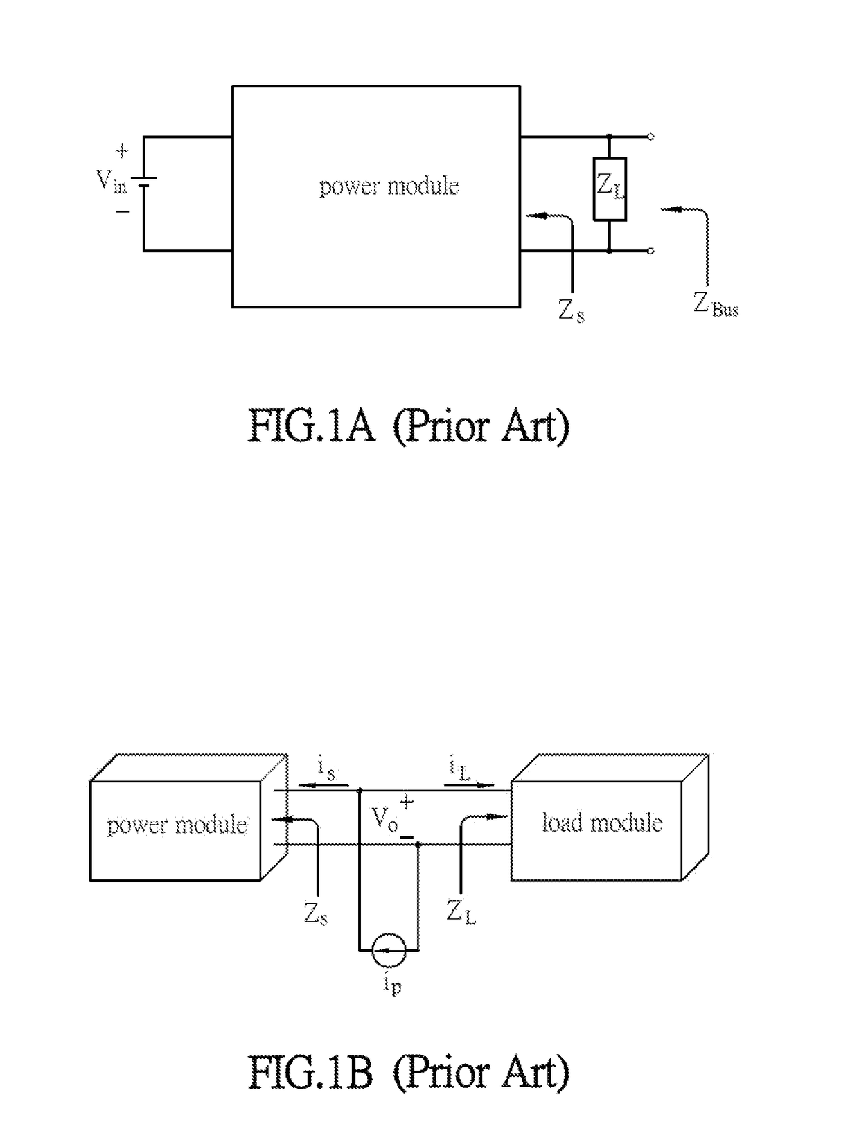
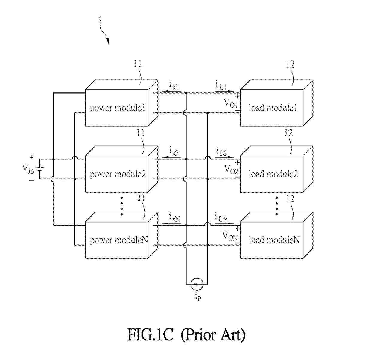
However, when the DC power system includes a parallel connection of multiple modules as shown in FIG. 1C, the difficulty in monitoring the stability thereof will increase. FIG. 1C is a schematic diagram of a conventional DC power system 1.
However, there is a large number of the power modules 11 and load modules 12, so the complexity and difficulty for monitoring is increased a lot.
Besides, this kind of monitoring belongs to an invasive manner, thus forbidden in the practical application.

Method used


Image

  • Non-invasive impedance analyzing apparatus and method
  • Non-invasive impedance analyzing apparatus and method
  • Non-invasive impedance analyzing apparatus and method

Examples


Embodiment Construction

[0045]The present invention will be apparent from the following detailed description, which proceeds with reference to the accompanying drawings, wherein the same references relate to the same elements.

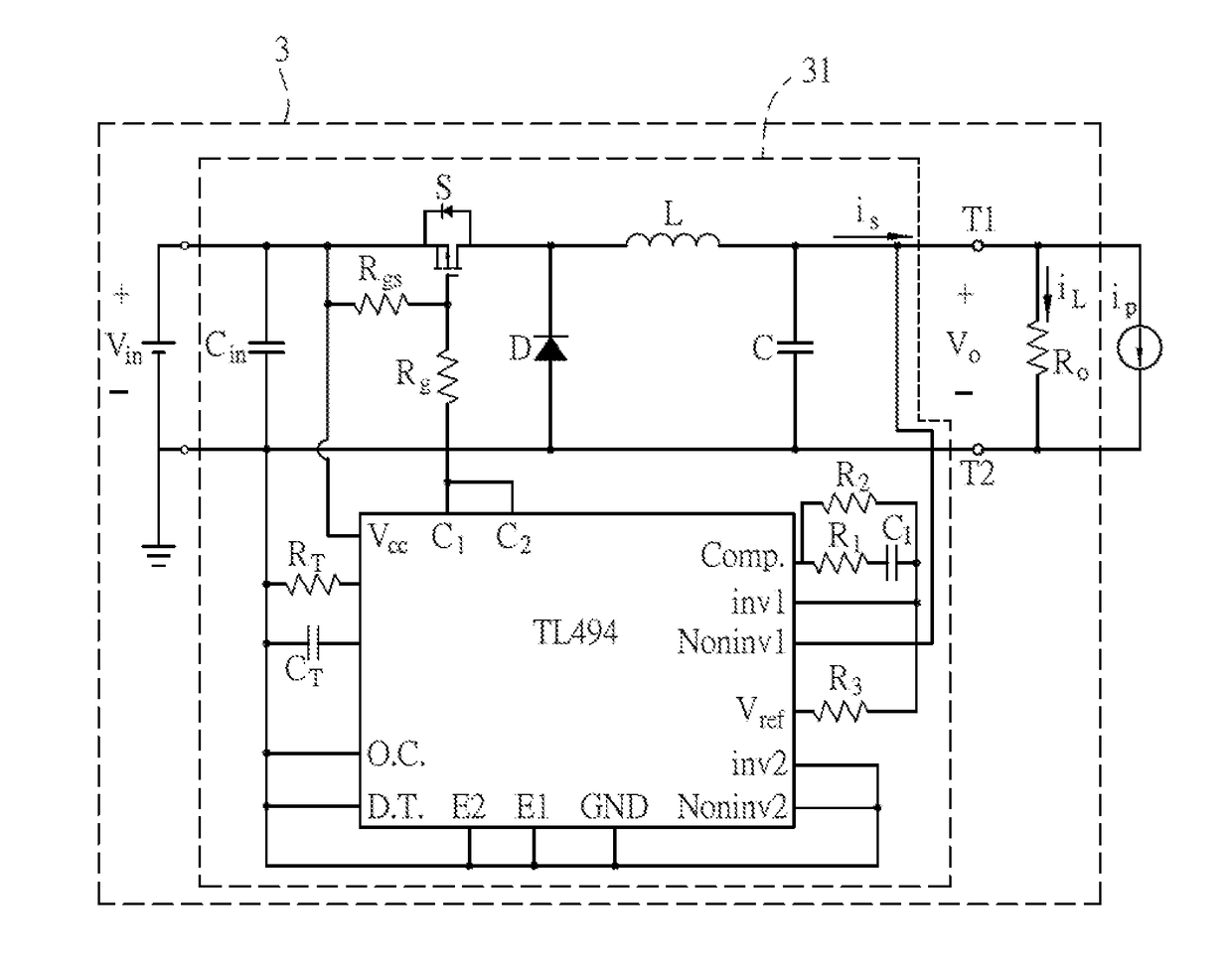
[0046]FIG. 2A is a schematic block diagram of a stability analyzing apparatus 2 according to a preferred embodiment of this invention in cooperation with a direct current (DC) power system 1, and FIG. 2B is a simplified equivalent circuit diagram of the DC power system 1 in FIG. 2A.

[0047]In FIGS. 2A and 2B, the stability analyzing apparatus 2 is in cooperation with the DC power system 1, which includes at least a power module 11 and at least a load module 12 as shown in FIG. 1C. The power module 11 has a power converting circuit that at least has a buck converter, a buck-boost converter, a boost converter or their any combination. In order to conveniently analyze the stability, the above-mentioned converting circuit can be simplified as a parallel RLC loop (i.e. a Norton equivalent ci...


PUM


Abstract

A stability analyzing apparatus is in cooperation with a DC power system having a bus terminal connected to at least a load, and comprises a perturbation signal generating module, a signal processing module and a determining module. The perturbation signal generating module generates a perturbation signal injected into the bus terminal to obtain a transfer function of the bus terminal impedance. The signal processing module is electrically connected to the perturbation signal generating module and calculates the slope of the transfer function of the bus terminal impedance to obtain a transfer function of the bus terminal impedance slope. The determining module is electrically connected to the signal processing module and determines the stability tendency of the DC power system according to the transfer function of the bus terminal impedance slope. A stability analyzing method is also disclosed.

Description

CROSS REFERENCE TO RELATED APPLICATIONS[0001]This application is a continuation application of U.S. Ser. No. 13 / 927,991, filed Jun. 26, 2013, which claims priority under 35 U.S.C. §119(a) on Patent Application No(s). 102113997, filed in Taiwan, Republic of China on Apr. 19, 2013, the entire contents of which are hereby incorporated by reference.BACKGROUND OF THE INVENTION[0002]Field of Invention[0003]The invention relates to a stability analyzing apparatus and stability analyzing method and, in particular, to a stability analyzing apparatus and stability analyzing method of a direct current (DC) power system.[0004]Related Art[0005]Because the DC power system has advantages of high reliability, good modular design and easy maintenance, it has been widely applied to many appliances, such as a DC grid system or a telecommunication system. For the large-scale DC distributed power system, monitoring the stability thereof is very important in order to avoid potential power failure.[0006]F...

Claims


Application Information

Patent Timeline
Patent Type & Authority Applications(United States)
IPC IPC(8): G01R27/30G05F1/46
CPCG05F1/46G01R27/30G05F1/10
Inventor LIN, RAY-LEECHEN, WEI-RU
Owner NAT CHENG KUNG UNIV
Learn More