Uterine manipulator device with cutting element

a technology of manipulator and cutting element, which is applied in the field of manipulator device for uterus, can solve the problems of affecting the surgeon's view of the operative field, reducing the diameter of the cannula used to cycle gas while distending the abdominal cavity, and the high degree of precision required, so as to minimize the number of tools needed, minimize the possibility of cauterization errors, and improve the identification of the specific area

Active Publication Date: 2017-06-08
ADAJAR ALLAN A
View PDF7 Cites 19 Cited by
  • Summary
  • Abstract
  • Description
  • Claims
  • Application Information

AI Technical Summary

Benefits of technology

[0014]The cervical cup may include a light source to illuminate the surgeon's operative field. The light source may comprise a fiber optic or a plurality of light emitting diodes that are secured to the rim of the cervical cup. During a surgical procedure, the operative field is viewed through a camera within the abdominal cavity. The light source on the uterine manipulator device transilluminates the cervix so that the surgeon can determine where the cervical cup is located. The transillumination also allows the surgeon to identify pelvic anatomy such as the uterine arteries and the ureter.
[0018]An objective of the present design is to minimize the number of tools necessary for a hysterectomy or related procedure by incorporating the cutting or cauterization tool into the uterine manipulator device.
[0019]An advantage of the present design is to minimize potential errors in cauterization by providing a stable surface in the cervical cup against which the heated element, cauterization wire, or cutting tool is secured.
[0020]A further advantage of the present application is the improved identification of the specific area to be cut or cauterized as well as the pelvic anatomy to be protected and avoided during a surgical procedure through the use of transillumination.
[0021]Another advantage of the present design is to provide adequate air flow through the abdominal cavity with sufficiently sized lumens or cannulas.

Problems solved by technology

In procedures involving the cauterization of tissue, smoke created by the cauterization may hinder the surgeon's view of the operative field.
However, decreasing the diameters of the cannulas used to cycle gas while distending the abdominal cavity is limited by the requirement for adequate air flow, as the air flow rate is directly proportional to the cannula diameter.
Manipulating the cutting element from outside of the body compounded by the high degree of precision required is difficult by even the most experienced surgeon's standards.
However, such devices cannot transilluminate the upper vagina to identify the location of the ureters and its proximity to the uterine vessels while providing insufflation and smoke evacuation.

Method used


Image

  • Uterine manipulator device with cutting element
  • Uterine manipulator device with cutting element
  • Uterine manipulator device with cutting element

Examples


Embodiment Construction

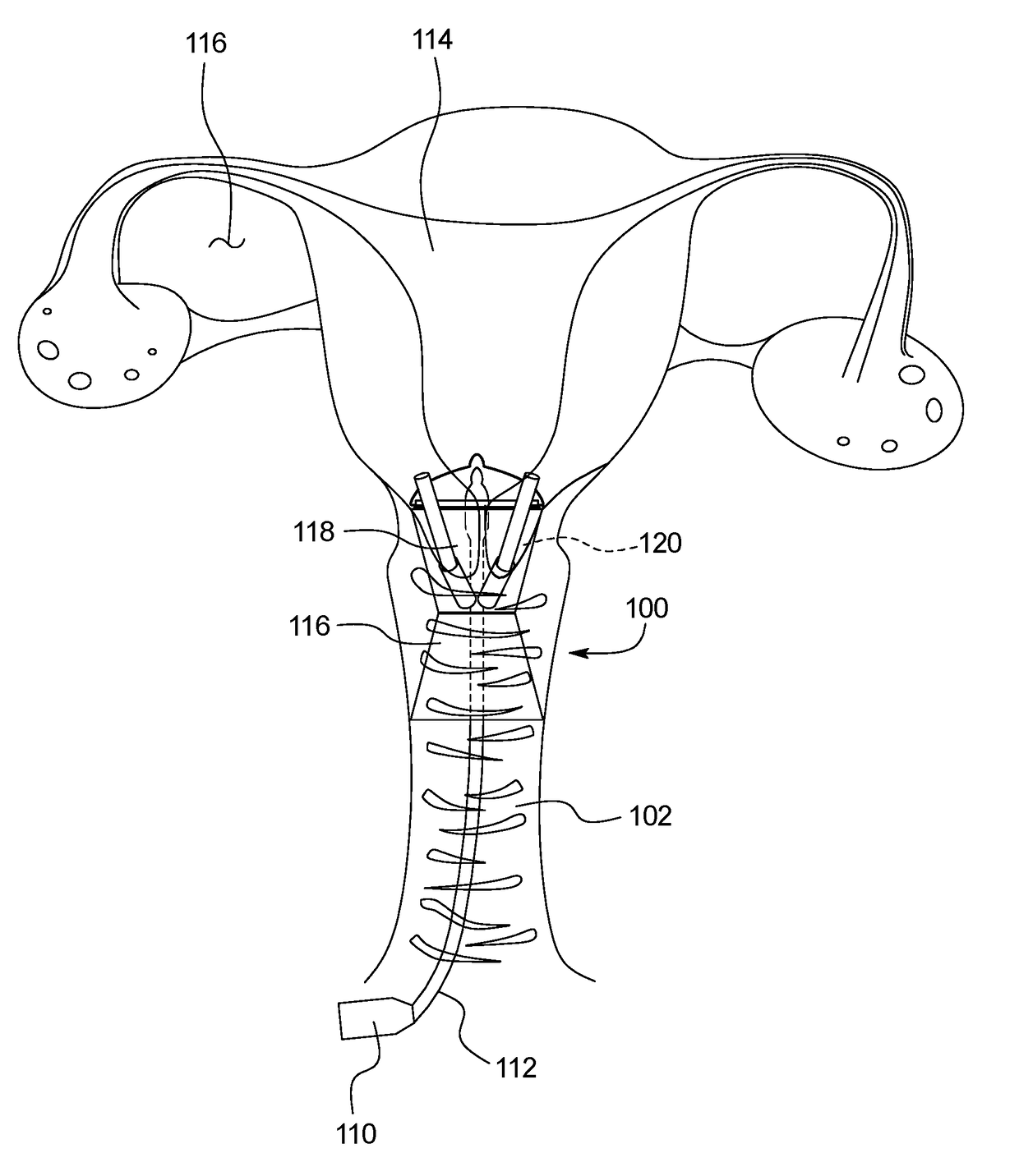
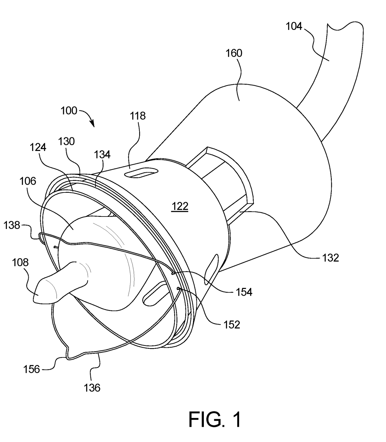
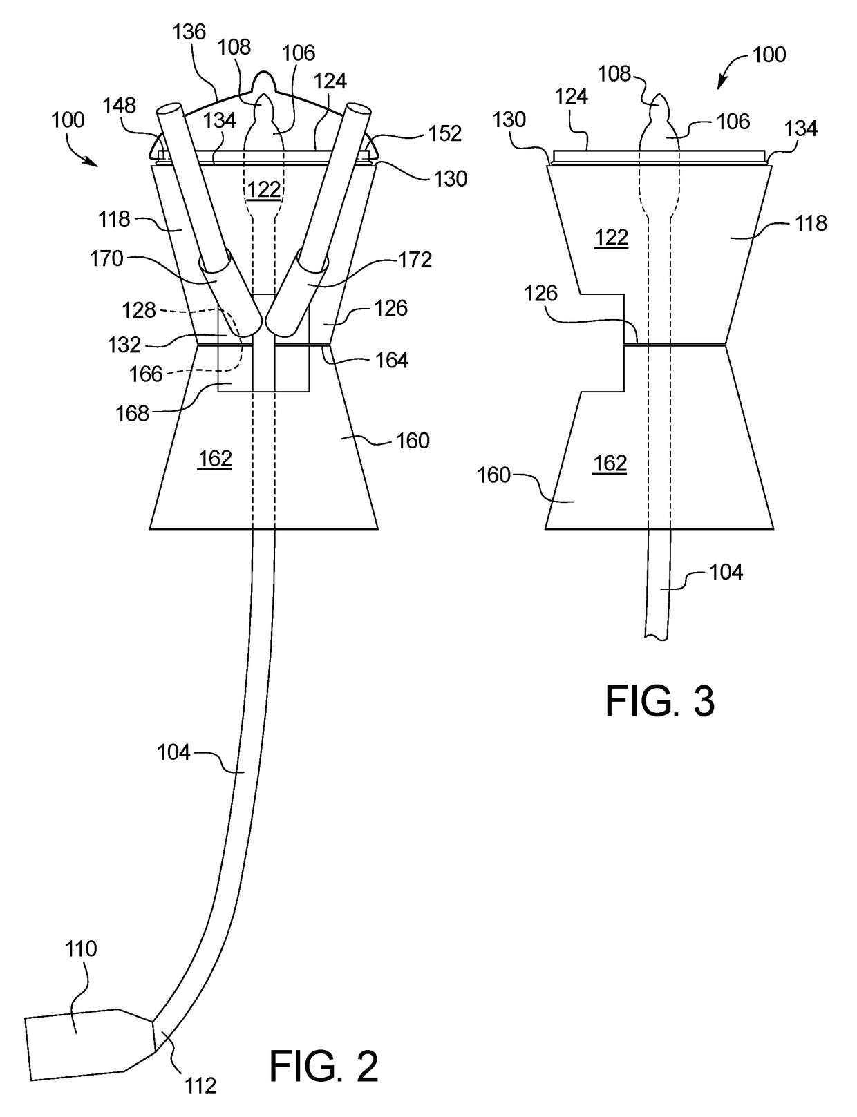
[0033]FIGS. 1-4 illustrate a uterine manipulator device 100 that is inserted through a patient's vaginal canal 102 during female pelvic surgery. The uterine manipulator device 100 includes a rigid shaft 104 with a balloon 106 positioned at a distal end 108. A handle 110 may be attached to a proximal end 112 of the shaft 104. During a procedure, the deflated balloon 106 is inserted into the patient's uterus 114 and then filled with water or other fluid. Separately, a camera inserted laparoscopically into the abdominal cavity 116 provides a view of the operative field, and the surgeon can move the uterus 114 by manipulating the handle 110 of the shaft 104 in order to view anatomy around the uterus 114 through the camera imaging.

[0034]Referring to FIG. 4, a cervical cup 118 is positioned on the shaft 104 adjacent the distal end 108 and receives the cervix 120 during use. Seen best in FIGS. 2 and 3, an annular wall 122 having a frustoconical shape with a rim 124 extends from a base 126....


PUM


Abstract

A uterine manipulator device includes a shaft including a proximal end and a distal end, a cervical cup positioned on the shaft near the distal end, and a cutting tool. The cervical cup includes a first base and an annular wall with a rim. The cutting tool positioned along the rim of the cervical cup is rotatably coupled to the rim.

Description

CROSS-REFERENCE TO RELATED APPLICATIONS[0001]This application incorporates by reference and claims the benefit of priority to U.S. Provisional Application No. 62 / 262,995 filed on Dec. 4, 2015.BACKGROUND OF THE INVENTION[0002]The present invention relates to a device for manipulating the uterus that delivers and removes gas from the patient's abdominal cavity during a laparoscopic surgical procedure. More specifically, the present invention relates to a device that efficiently transects the walls of the vagina while cycling gas through the cavity during a laparoscopic surgical procedure.[0003]During a hysterectomy, a patient's uterus and cervix are surgically removed from the body. Utilization of the vaginal canal for abdominal access to reproductive organs is conventional in gynecologic surgery to minimize or eliminate the need to make incisions in the patient's skin. The use of laparoscopic or “minimally invasive” surgical procedures is becoming more common because of the reduced p...

Claims


Application Information

Patent Timeline
Patent Type & Authority Applications(United States)
IPC IPC(8): A61B17/42A61B17/3209A61M29/02A61B18/10A61B1/313A61B1/05A61B1/07A61B18/08
CPCA61B17/4241A61B1/07A61B17/3209A61B18/082A61B18/10A61B2017/00734A61B1/05A61M29/02A61B2017/4225A61B2018/00595A61B2018/00559A61B1/3132A61B17/3474A61B2218/006A61B2090/309A61B2090/306
Inventor ADAJAR, ALLAN A.
Owner ADAJAR ALLAN A
Why Eureka
Try Eureka