
Lead-acid accumulator and method for manufacturing such an accumulator

a technology of lead-acid accumulators and accumulators, which is applied in the direction of cell components, final product manufacturing, sustainable manufacturing/processing, etc., can solve the problems of limited active material use, limited lifetime of accumulators, and significant weight of lead current collectors, etc., and achieves high specific energy and extended life

Inactive Publication Date: 2017-06-01
COMMISSARIAT A LENERGIE ATOMIQUE ET AUX ENERGIES ALTERNATIVES
View PDF0 Cites 3 Cited by
  • Summary
  • Abstract
  • Description
  • Claims
  • Application Information

AI Technical Summary

Benefits of technology

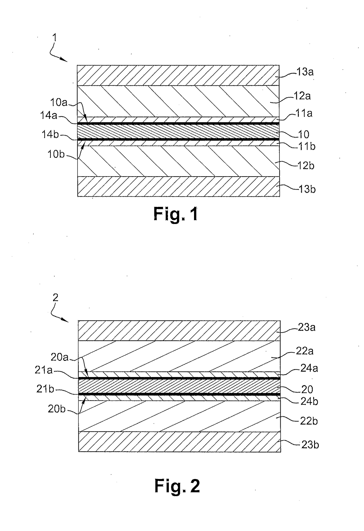
The invention provides an electrochemical lead-acid accumulator with a negative electrode and a positive electrode that have high specific energy and long lifespan. The negative electrode has a carbon sheet with a thickness of 50 μm to 200 μm and first and second lead-based layers covering its faces. The positive electrode has a titanium sheet with a thickness of 50 μm to 250 μm and first and second metal oxide layers covering its faces. The negative and positive electrodes are separated by at least one sheet of an electrically insulating porous material. The accumulator may have a spiral shape or a serpentine shape. The method for manufacturing the accumulator involves depositing layers on the carbon sheet and titanium sheet and assembling them with the insulating porous material. The technical effect of the invention is to provide an electrochemical lead-acid accumulator with improved performance and durability.

Problems solved by technology

This energy density value results from the significant weight of lead current collectors and a limited use of the active materials.
Nevertheless, on account of the low thickness of the lead sheets, the lifetime of the accumulator is limited.
In fact, the current collector of the positive electrode is subject to a phenomenon of corrosion, the lead is gradually converted into lead dioxide.
Yet, lead dioxide is fragile, which can imply a loss of dimensional stability.
Furthermore, the use of voluminous lead connectors limits the mass energy density of the accumulator (of the order of 30 Wh / kg).
However, this battery shows a limited lifetime, because the positive electrode degrades over charge and discharge cycles.
Whatever the geometry proposed and the nature of the electrodes, none of the solutions proposed until now has made it possible to obtain simultaneously high mass energy density and long lifetime.

Method used


Image

  • Lead-acid accumulator and method for manufacturing such an accumulator
  • Lead-acid accumulator and method for manufacturing such an accumulator
  • Lead-acid accumulator and method for manufacturing such an accumulator

Examples


first embodiment

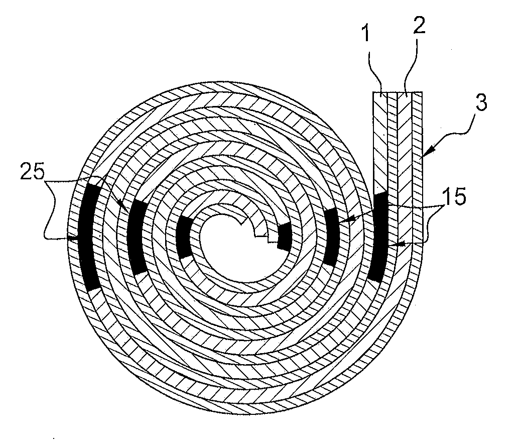
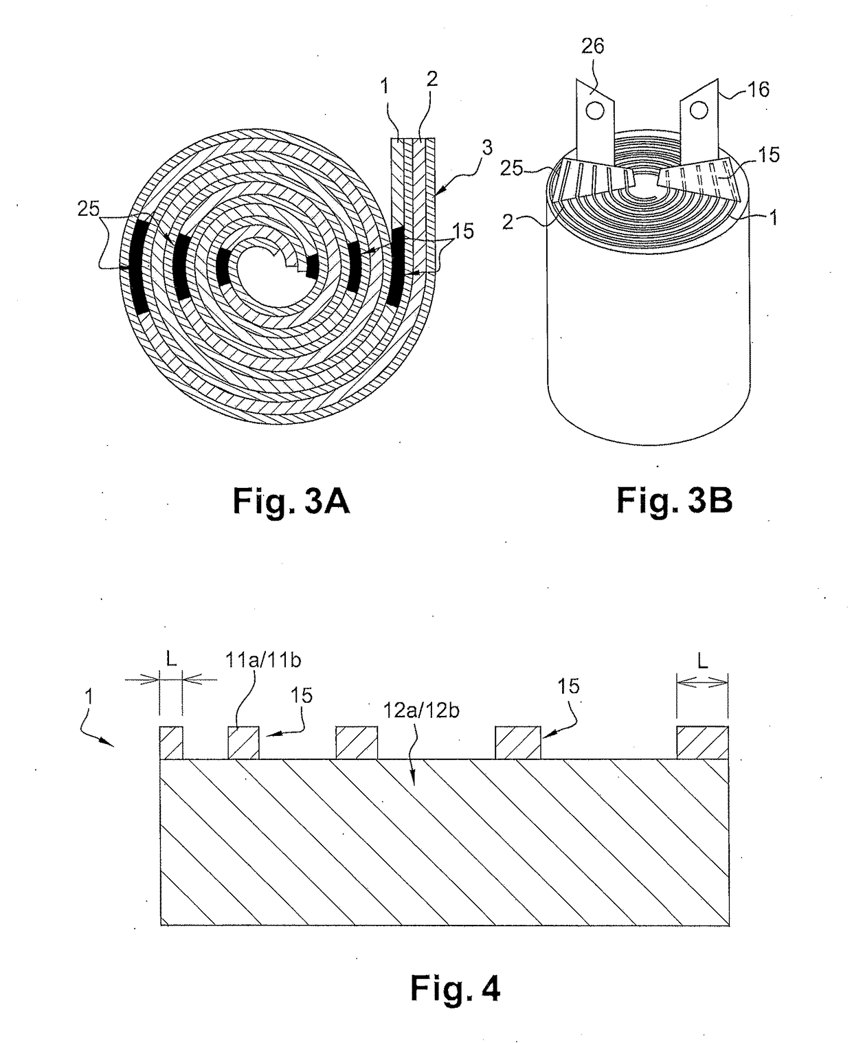
[0099] represented by FIGS. 3A and 3B, respectively in top view and perspective view, the negative 1 and positive 2 electrodes are stacked with two separator sheets 3 formed from the porous and insulating material. This multilayer stack is wound upon itself to give the accumulator a spiral shape.

[0100]The sheets 3 are arranged such that at any point of the winding, one of them separates the negative 1 and positive 2 electrodes. Thus, no short-circuit between the electrodes 1 and 2 is possible and the utilization factor of the electrolyte is maximal. The two separator sheets 3 are for example arranged on either side of the positive electrode 2 in FIG. 3A.

[0101]The separator sheets 3 are, preferably, of AGM (Adsorptive Glass Mat) type, that is to say microporous glass fibers layers. This type of separator is commonly employed in valve regulated lead acid (VRLA) batteries to store the electrolyte and maintain the active material on the electrodes. The sheets 3 have, preferably, a thick...

second embodiment

[0121]FIG. 5 represents, in top view, a lead accumulator, in which the electrodes 1 and 2 are assembled in an undulating shape, in the manner of a serpentine shape. The electrochemical accumulator thus configured is like a prismatic cell, where the positive and negative electrode(s) are lined up in parallel with each other in a parallelepiped case.

[0122]One of the positive and negative electrodes, here the negative electrode 1, is arranged between two separator layers 3, preferably of AGM type. The multilayer stack thereby obtained is folded into a serpentine shape, that is to say in a repeating manner and in opposing senses from one fold 4 to the other. Under each fold 4 is arranged a portion 2′ of positive electrode. These portions 2′ are for example obtained after cutting up a positive electrode 2 of larger dimensions.

[0123]The electrodes of the accumulator also have, in this second embodiment, projecting straps or connection elements 15 and 25. These straps extend in a direction...


PUM

PropertyMeasurementUnit
thicknessaaaaaaaaaa
thicknessaaaaaaaaaa
thicknessaaaaaaaaaa

Abstract

An electrochemical lead-acid accumulator includes negative and positive electrodes. The negative electrode has a current collector formed from a carbon sheet having a thickness between 50 and 200 μm; first and second lead-based layers respectively covering first and second faces of the carbon sheet; and first and second layers of a lead-containing active material, having a thickness between 100 and 500 μm, and arranged on either side of the carbon sheet, respectively on first and second lead-based layers. The positive electrode has a current collector formed from a titanium sheet having a thickness between 50 and 250 μm; first and second electrically conducting metal oxide layers, respectively covering first and second faces of the titanium sheet; and first and second layers of a lead-containing active material, having a thickness comprised between 100 and 500 μm, arranged on either side of the titanium sheet, respectively on first and second metal oxide layers.

Description

TECHNICAL FIELD[0001]The present invention relates to an accumulator of lead-acid type used as electrochemical energy storage system, notably in the automobile field, and a method for manufacturing a lead-acid accumulator.STATE OF THE ART[0002]A lead-acid accumulator comprises a positive electrode and a negative electrode immersed in a sulphuric acid-based liquid electrolyte. Each electrode conventionally comprises a lead current collector on which is arranged a lead-based active material, typically porous lead dioxide for the positive electrode and porous lead for the negative electrode. The current collector, for example in grid or plate form, serves as mechanical support to the active material and assures the electrical connection between the active material of the electrode and a terminal of the accumulator. The chemical reactions taking place in the accumulator during discharging converts the lead dioxide (PbO2) of the positive electrode and the lead (Pb) of the negative electr...

Claims


Application Information

Patent Timeline
Patent Type & Authority Applications(United States)
IPC IPC(8): H01M10/12H01M4/16H01M4/38H01M4/56H01M4/36H01M2/26H01M4/68H01M50/534H01M50/538H01M50/541
CPCH01M10/125H01M2/263H01M4/16H01M4/38H01M4/56H01M4/366H01M4/68H01M10/12Y02E60/10H01M50/538Y02P70/50H01M50/534
Inventor KIRCHEV, ANGEL ZHIVKOVPERRIN, MARION
Owner COMMISSARIAT A LENERGIE ATOMIQUE ET AUX ENERGIES ALTERNATIVES
Learn More