
3-level power topology

Active Publication Date: 2017-05-25
SCHNEIDER ELECTRIC IT CORP
View PDF7 Cites 13 Cited by
  • Summary
  • Abstract
  • Description
  • Claims
  • Application Information

AI Technical Summary

Benefits of technology

The invention is about a power supply system that converts input AC power into converted DC power, which is then converted into output AC power by an inverter. The system includes a first DC bus and a second DC bus, and a controller that synchronizes the switching of the converter and inverter to achieve zero voltage switching (ZVS) at the output. The system can also include a DC / DC converter and a second DC bus to provide regulated DC power to the first DC bus. The technical effect of the invention is to improve the efficiency and reliability of power conversion in a power supply system.

Problems solved by technology

Since the DC bus is powered either by mains or the battery, the output power of the UPS is uninterrupted if the mains fails and the battery is sufficiently charged.

Method used


Image

  • 3-level power topology
  • 3-level power topology
  • 3-level power topology

Examples


Embodiment Construction

[0024]Examples of the methods and systems discussed herein are not limited in application to the details of construction and the arrangement of components set forth in the following description or illustrated in the accompanying drawings. The methods and systems are capable of implementation in other embodiments and of being practiced or of being carried out in various ways. Examples of specific implementations are provided herein for illustrative purposes only and are not intended to be limiting. In particular, acts, components, elements and features discussed in connection with any one or more examples are not intended to be excluded from a similar role in any other examples.

[0025]Also, the phraseology and terminology used herein is for the purpose of description and should not be regarded as limiting. Any references to examples, embodiments, components, elements or acts of the systems and methods herein referred to in the singular may also embrace embodiments including a pluralit...


PUM


Abstract

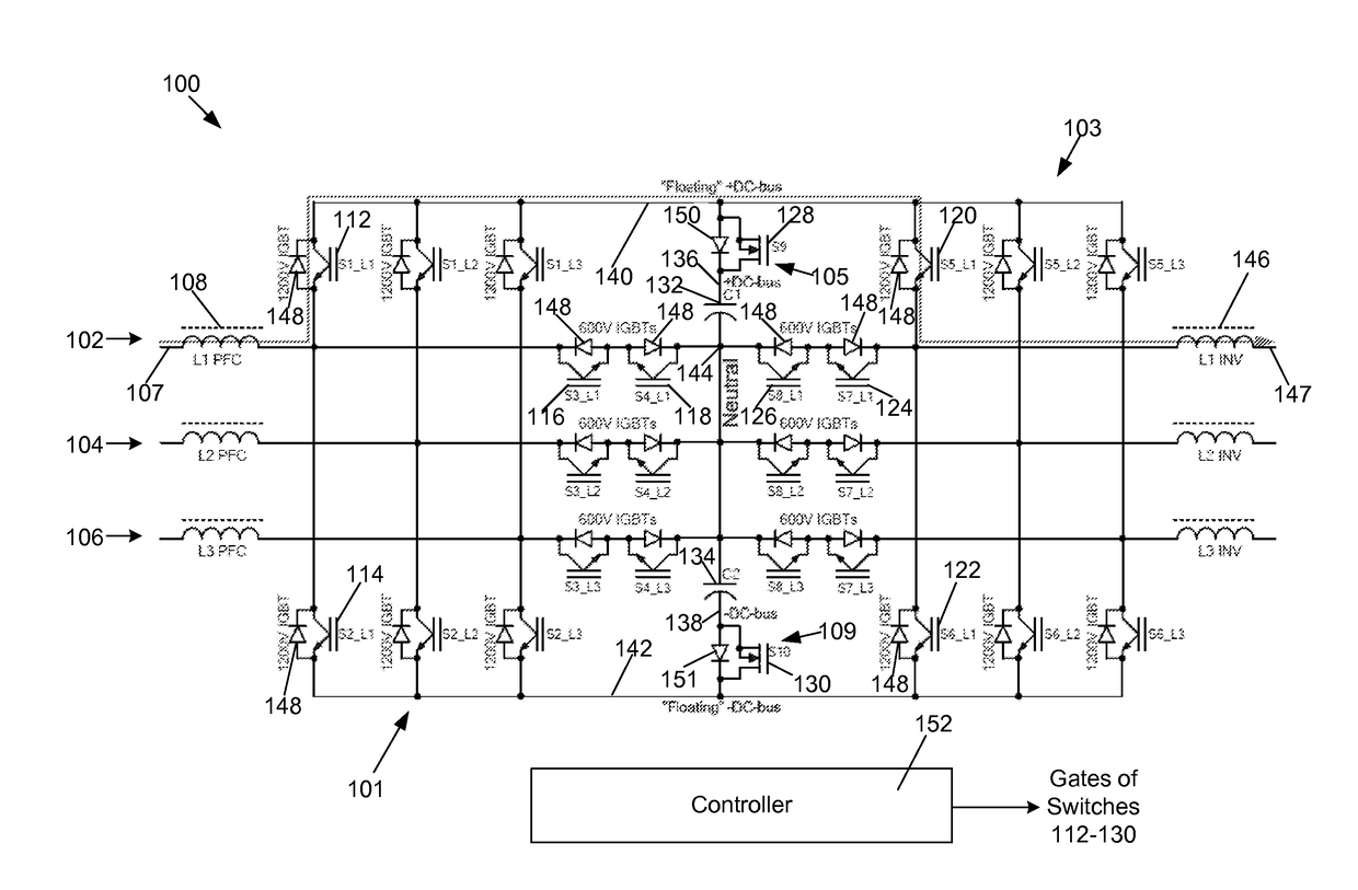
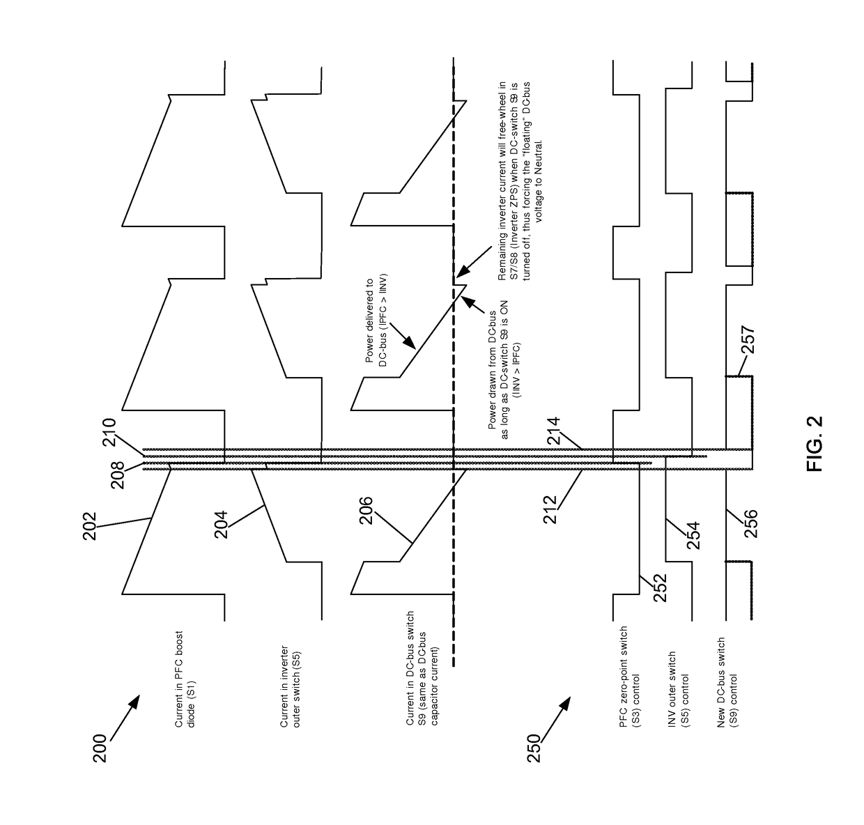
According to one aspect, embodiments of the invention provide a power supply system comprising an input configured to receive input AC power from an input power source, an output configured to provide output AC power to a load, a converter coupled to the input and configured to convert the input AC power into converted DC power, a first DC bus coupled to the converter and configured to receive the converted DC power, an inverter coupled to the first DC bus and the output and configured to convert DC power from the first DC bus into the output AC power, a first DC switch circuit coupled between the first DC bus and neutral and a controller coupled to the first DC switch circuit and configured to operate the first DC switch circuit such that voltage on the first DC bus is zero during switching operation of the converter and the inverter.

Description

BACKGROUND[0001]1. Field of the Disclosure[0002]Embodiments of the present disclosure relate generally to systems and methods for providing power.[0003]2. Description of Background[0004]A power supply, such as an uninterruptible power supply (UPS) is typically used to provide power to an electrical device or load. A UPS can provide power while a primary power source, or mains, is unavailable. A conventional online UPS rectifies input power provided by an electric utility using a Power Factor Correction circuit (PFC) to provide power to a DC bus. The rectified DC voltage is typically used to charge a battery while mains power is available, as well as to provide power to the DC bus. In the absence of mains power, the battery provides power to the DC bus. From the DC bus, an inverter generates an AC output voltage to the load. Since the DC bus is powered either by mains or the battery, the output power of the UPS is uninterrupted if the mains fails and the battery is sufficiently charg...

Claims


Application Information

Patent Timeline
IPC IPC(8): H02M5/458H02M1/088
CPCH02M5/4585H02M2001/0058H02M1/088H02M1/4216H02M7/487H02M1/0058Y02B70/10H02J9/063
Inventor MOURIDSEN, JONAS SONSBY
Owner SCHNEIDER ELECTRIC IT CORP
Learn More