
Amoled ir drop compensation system and method

a technology of amoled and ir drop, applied in the field of display technology, can solve the problems of poor image homogeneity and affect the quality of displayed images

Active Publication Date: 2017-05-18
SHENZHEN CHINA STAR OPTOELECTRONICS TECH CO LTD
View PDF5 Cites 5 Cited by
  • Summary
  • Abstract
  • Description
  • Claims
  • Application Information

AI Technical Summary

Benefits of technology

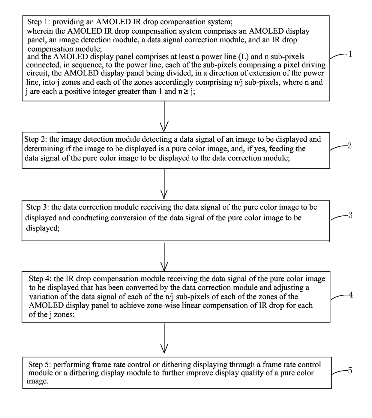
The present invention provides an AMOLED IR drop compensation system and method to effectively compensate for the problem of image quality being not homogeneous caused by IR drop when displaying a pure color image. This is achieved by dividing the AMOLED display panel into multiple zones and using an image detection module to determine if an image is a pure color image. A data signal correction module converts the data signals of the pure color image to be displayed, while an IR drop compensation module adjusts the data signals of each zone to conduct zone-wise linear IR drop compensation. The algorithm is easy for simple implementation.

Problems solved by technology

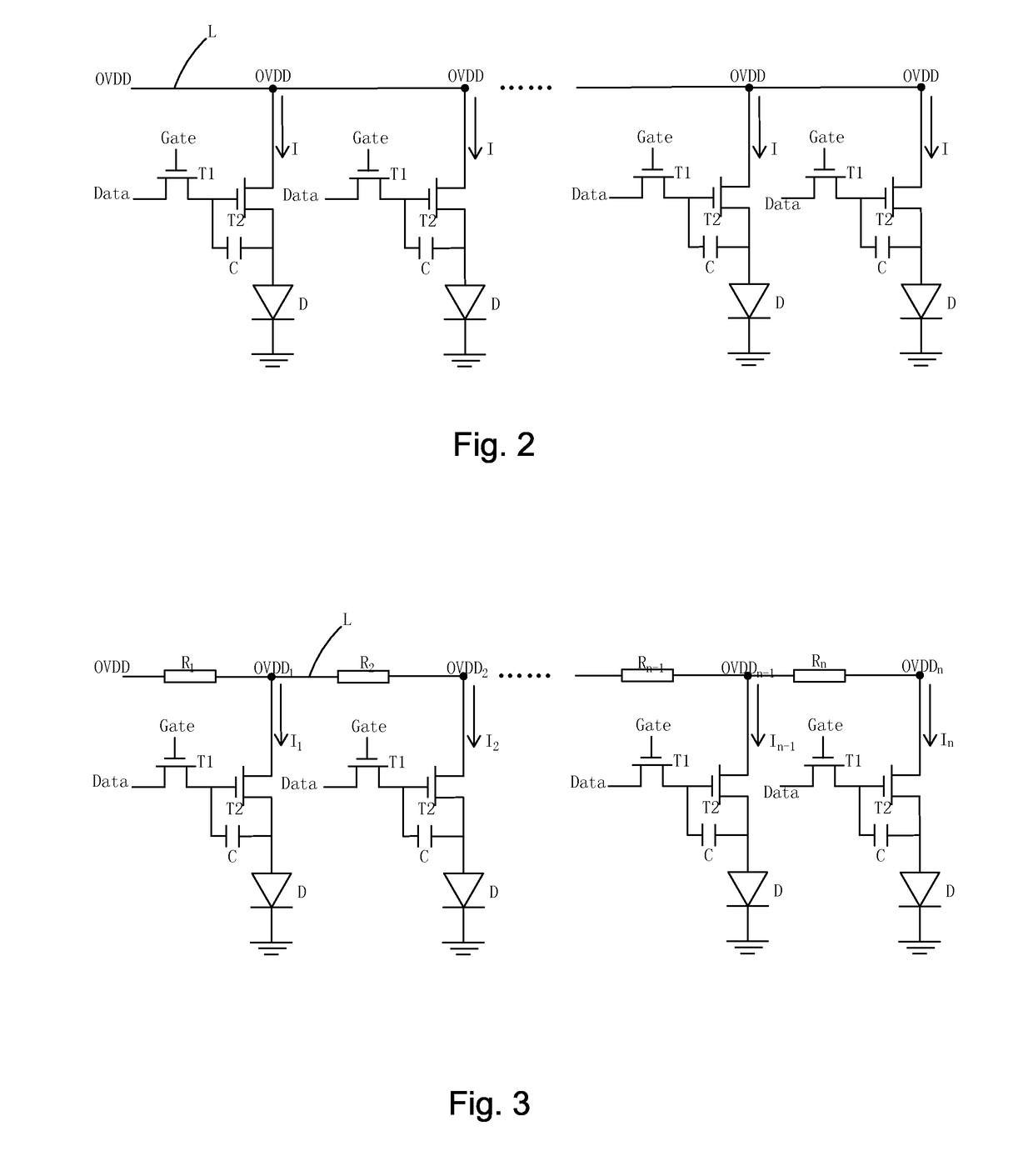
In displaying a pure color, since the electrical current Ii that flows through the ith pixel driving circuit is related to the source voltage OVDDi, different pixels have different outputs of electrical current, leading to different levels of brightness at different areas of a display panel so that the image homogeneity is poor and the displayed image quality is affected.

Method used


Image

  • Amoled ir drop compensation system and method
  • Amoled ir drop compensation system and method
  • Amoled ir drop compensation system and method

Examples


Embodiment Construction

[0066]To further expound the technical solution adopted in the present invention and the advantages thereof, a detailed description is given to a preferred embodiment of the present invention and the attached drawings.

[0067]Referring to FIGS. 4-6, firstly, the present invention provides an active matrix organic light emitting diode (AMOLED) IR drop compensation system, which comprises an AMOLED display panel, an image detection module, a data signal correction module, and an IR drop compensation module.

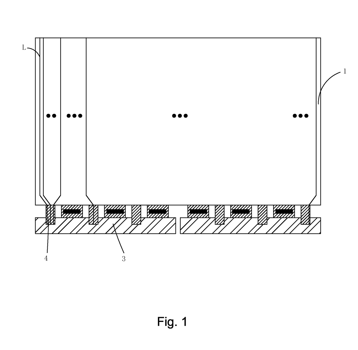
[0068]The AMOLED display panel comprises at least a power line L and n sub-pixels connected, in sequence, to the power line. Each of the sub-pixels comprises a pixel driving circuit. The AMOLED display panel is divided, in a direction of extension of the power line, into j zones and each of the zones accordingly comprises n / j sub-pixels, where n and j are each a positive integer greater than 1 and n≧j. Specifically, as shown in FIG. 5, if the power line L extends in a vertical directi...


PUM


Abstract

The present invention provides an AMOLED IR drop compensation system and method. The AMOLED IR drop compensation system includes an AMOLED display panel that is divided into a plurality of zones, an image detection module, a data signal correction module, and an IR drop compensation module and may achieve zone-wise linear compensation for IR drop. The AMOLED IR drop compensation method includes dividing an AMOLED display panel in a direction of extension of a power line into a plurality of zones, applying an image detection module to detect a data signal of an image to be displayed and determine if the image to be displayed is a pure color image, applying a data correction module to convert the data signal of a pure color image to be displayed, and applying an IR drop compensation module to conduct zone-wise linear IR drop compensation for each of the plurality of zones by adjusting the variation of the data signal of each of the sub-pixels of each of the zones of the AMOLED display panel. The present invention can effectively compensate IR drop and overcome the problem of the image quality being not homogeneous caused by IR drop when an AMOLED display panel is displaying a pure color image.

Description

BACKGROUND OF THE INVENTION[0001]1. Field of the Invention[0002]The present invention relates to the field of display technology, and in particular to an active matrix organic light-emitting diode (AMOLED) IR drop compensation system and method.[0003]2. The Related Arts[0004]Organic light emitting diode (OLED) display devices have various advantages, including being self-luminous, low driving voltage, high luminous efficiency, short response time, high resolution and contrast, approximately 180 degree view angle, wide operation temperature range, and being capable of flexible displaying and large-area full-color displaying, and is thus considered one of the display devices that have the most prosperous future.[0005]The OLED display devices can be classified in two types, which are passive matrix OLED (PMOLED) and active matrix OLED (AMOLED), namely direct addressing and thin-film transistor (TFT) matrix addressing, according to how it is driven. The AMOLED comprises pixels arranged ...

Claims


Application Information

Patent Timeline
IPC IPC(8): G09G3/3258G09G3/20
CPCG09G3/3258G09G3/2003G09G2300/0452G09G2320/0276G09G2330/021G09G2320/0673G09G2320/0233G09G3/3233G09G2320/0223G09G2320/0686G09G2360/16
Inventor XU, JINGHWANG, TAIJIUN
Owner SHENZHEN CHINA STAR OPTOELECTRONICS TECH CO LTD
Learn More