
Variable area blade turbine and conditioning flow deflectors device and method

a blade turbine and variable area technology, applied in the direction of machines/engines, engine components, hydropower generation, etc., can solve the problems of few economically feasible technologic alternatives, inability to connect rural communities to the interconnected system, and inability to provide electricity to rural communities. , to achieve the effect of increasing the mechanical complexity and the risk of system failure, easy stacking, and increasing the overall extended blade area

Inactive Publication Date: 2017-05-18
CORPORACION ANDINA DE FOMENTO
View PDF17 Cites 3 Cited by
  • Summary
  • Abstract
  • Description
  • Claims
  • Application Information

AI Technical Summary

Benefits of technology

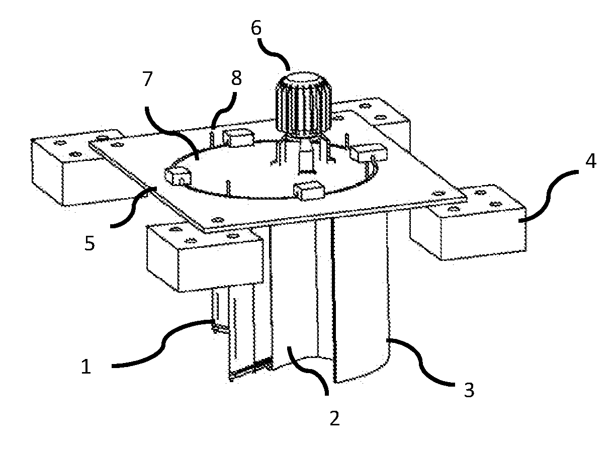
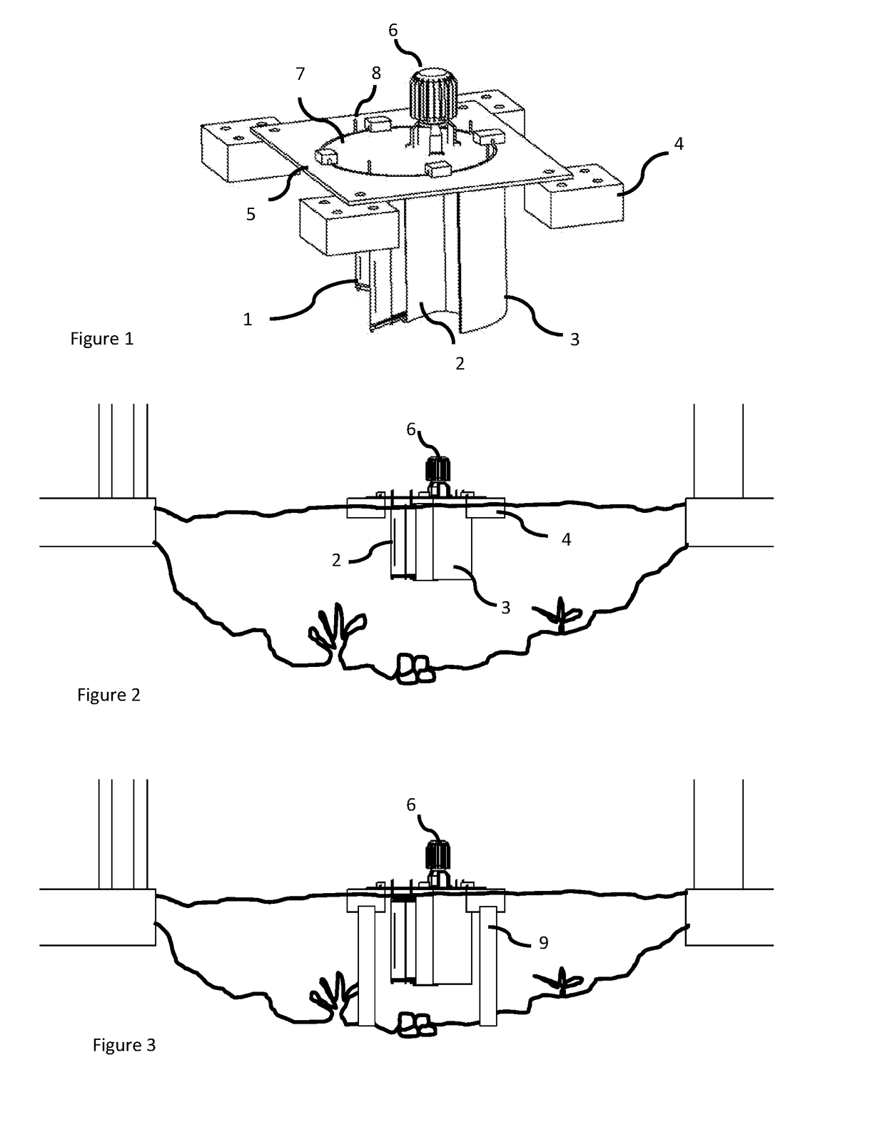
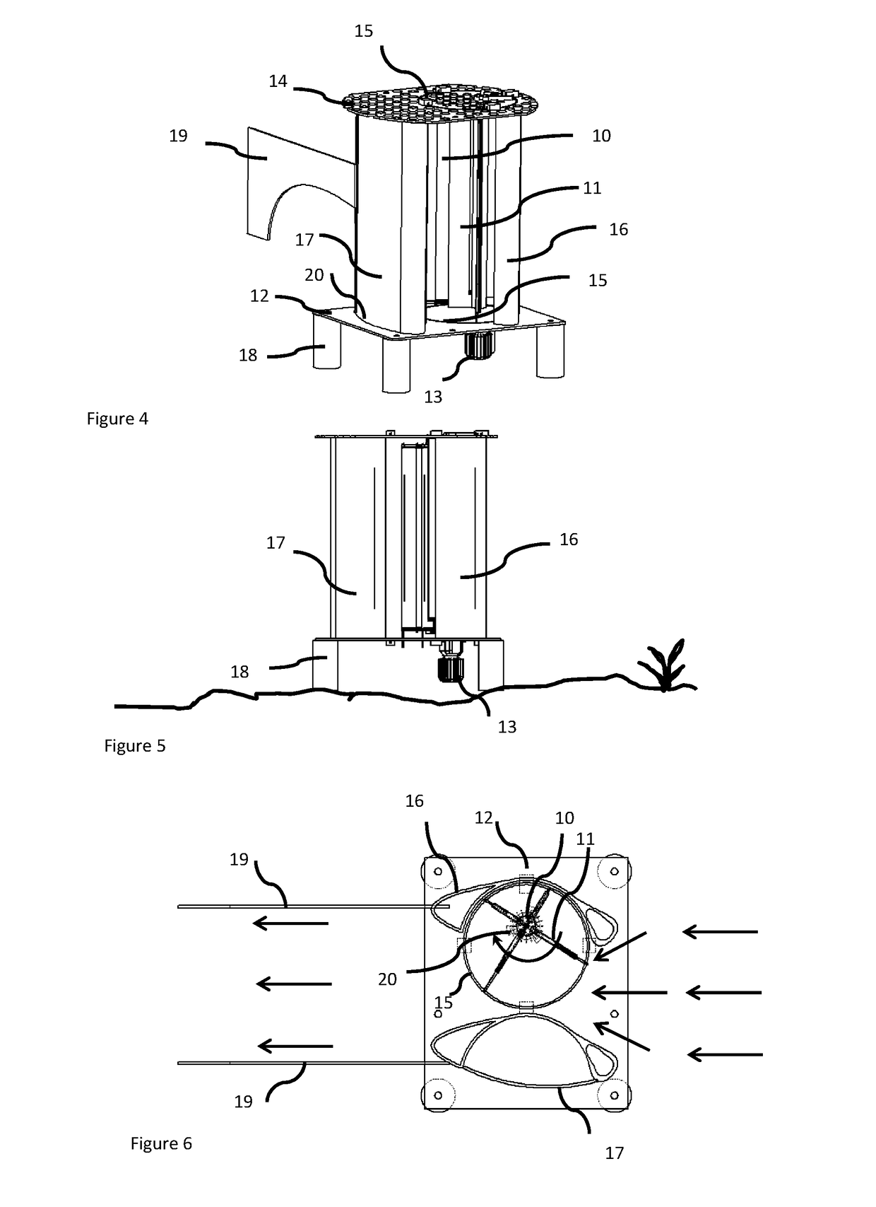
The present invention is a modular device that uses the energy of a fluid flow to generate power. It consists of a turbine with a rotor that is immersed in the flow and has blades that can adjust their area to increase the energy transfer and decrease the drag force. The device can be placed easily on any spot in a water channel without needing major construction. The main objective is to increase the efficiency and output power generation of this type of turbine.

Problems solved by technology

Electric power in these communities is usually provided by small diesel generators that are very costly to operate (diesel must be transported hundreds of kilometers through boats).
Given the geographic, ecologic, and climate characteristics, as well as the difficult access, areas such as the central part of the West Amazon basin have few economically feasible technologic alternatives to bring electricity to their communities.
The conventional network extension modality commonly used to provide electricity to rural communities and to connect them to the interconnected system is not feasible in these areas not only because of their distances, but also due to the density of the tropical forest, and how inaccessible and dispersed the communities are.
The use of this modality is only feasible in communities that are relatively close to departmental or provincial capitals that have isolated systems under concession.
Both types of turbines need a minimum speed of 1.5 m / s to work effectively, and this would limit its use in a great number of the rivers considered in the central area of the West Amazon basin, where the average speed of the flow of water is between 0.9 to 1.3 m / s.
Both types of turbines would also be exposed to the risk of being hit by floating material (trees, branches, roots, etc.), which is very common in Amazon rivers.

Method used


Image

  • Variable area blade turbine and conditioning flow deflectors device and method
  • Variable area blade turbine and conditioning flow deflectors device and method
  • Variable area blade turbine and conditioning flow deflectors device and method

Examples


first embodiment

[0089]FIG. 9 is a top view of a variable area blade turbine with only the rotor 34 of four blades 35a, 35b, 35c, 35d using the telescopic or nesting method, the blocking deflector 37, the base platform 38, and the fixed guide 36 located on a fluid flow. The rotor 34 rotates in clockwise direction as the fluid flows leftwards. The area swept by the four blades 35a, 35b, 35c and 35d attached to the rotor 34 is delimited by the circular curve in this case coincident with the fixed guide 36. There are four quadrants identified in that area, being the two quadrants limited by the curved segment DAB corresponding to the called “working region” because it is the region where the flow produce a force on the blades in the desired direction of rotation of the rotor, generating the working torque on the rotor. The two quadrants descripted by the curved segment BCD is called the “return region” in which the blades are not being moved by the flow, even receiving a force by the fluid in opposed d...

third embodiment

[0096]FIG. 14 is a cross sectional view of the variable area blade turbine showing two diametrically opposed blades using the area reorientation method. This method consists on having MBPs 64a and 64b with flat or airfoil like shape on each blade, rotating on its own longitudinal axis relative to the FBP 65a and 65b which bears their shaft in such a manner that during the pass of the blade through the “working region”, the MBPs 64a on the blade located rightwards to the spindle shaft 23, rotate to face the flow with the wider area, closing the pass of the flow between them, in a similar way to a blind curtain when it is closed to avoid the light to pass thru, maximizing the force of the fluid on that blade, and the MBP's 64b facing the flow with their thinner side, to allow the flow to pass through them, showing the blade at this point the minimal resistance to move. The movement of the MBP 64a and 64b is made by the radial displacement the followers 66a and 66b with respect to the ...

fourth embodiment

[0103]FIG. 21 is a partial plant view of the four blade rotor of the present invention as shown in FIG. 20 including the platform 101, and the fixed guides to restrain the movement of the followers, being the outer guide 102, the middle guide 103 and the inner guide 104, for each one of the respective followers 95, 96, 97 from FIG. 20. As the rotor turns, each follower displaces along its corresponding fixed guide, changing the relative distance between each pair of two consecutive followers of the same blade, and this change in distance due to the eccentricity of the fixed guides 102, 103, 104. The geometrical profile of the fixed guides may be any closed curve, preferably mathematically soft, which means each segment of the curve is tangent with its colliding segment and are continuous, being possible to have some portions of such curve as straight lines. As example of the geometrical profile of the fixed guides is shown by circular elements in the fixed guides 102, 103, 104. The ...


PUM


Abstract

A mechanism to provide controlled variable area blades for fluid driven tangential turbines is disclosed, where the spindle axis is perpendicular to the fluid flow, applicable in vertical axis hydraulic turbines but extensive to horizontal axis or wind turbines, with the rotor completely immersed on the flow. Each blade varying its area at selected position of the rotor turning, increasing to maximize conversion of the kinetic energy of the fluid onto mechanical rotational power of the shaft, or reducing to minimize drag moving opposed to such current. A comprehensive method is provided to control the variation in area for any specific degree of rotation of the turbine shaft on a rotational blade array, different flow conditioning deflector solutions in order to increase the power generation capability of the turbine, by increasing speed of the incoming flow to the rotor and minimizing drag of the returning blades.

Description

CROSS REFERENCE TO RELATED APPLICATION[0001]This application claims the benefit of priority of U.S. Provisional Patent Application No. 62 / 255,872, filed on Nov. 16, 2015, application which is incorporated herein in its entirety for all purposes.BACKGROUND OF THE INVENTION[0002]The development and marketing of hydrokinetic renewable energy technologies of low (5 kW) and medium (250 kW) power to provide energy to isolated rural communities near navigable rivers in basins around the world, such as the West Amazon basin and others in Africa and Asia, is a short-term priority due to the high costs of electric energy in isolated communities in these basins. Currently, the governments of these regions are interested in improving the quality of life of communities there, and in reducing the high subsidies that are currently being used to provide energy to these areas. Electric power in these communities is usually provided by small diesel generators that are very costly to operate (diesel m...

Claims


Application Information

Patent Timeline
IPC IPC(8): F03B3/14F03B3/18
CPCF03B3/145F05B2220/32F03B3/18F05B2240/93F05B2240/91F05B2240/13F03B17/067Y02E10/20
Inventor VISIERS DE TORAN, CONCEPCIONTORAN, JOSE
Owner CORPORACION ANDINA DE FOMENTO
Learn More