Flexible impeller pump

a flexible, impeller technology, applied in the direction of liquid fuel engines, machines/engines, manufacturing tools, etc., can solve the problems of dual-cam flexible impellers, inability to successfully implement them, increase pressure, etc., to reduce the angular distance occupied by the cammed sealing surface, the effect of increasing the maximum pumping pressur

Pending Publication Date: 2017-05-11
MARINE FLOW
View PDF8 Cites 4 Cited by
  • Summary
  • Abstract
  • Description
  • Claims
  • Application Information

AI Technical Summary

Benefits of technology

The invention allows for a pump with a smaller distance between the inlet and outlet, which reduces leakage. This is achieved by using a seal created by the pump's vane(s) which prevents pressure from escaping from the outlet to the inlet. The design also allows for the simultaneous removal of the hub and impeller using only one tool, making the installation process easier.

Problems solved by technology

The vanes are deflected when they make contact with the cam and this creates an increase in pressure, thus ‘squeezing’ the fluid being pumped out of the pump housing and out of the outlet.
Dual-cam flexible impeller pumps, i.e. those having two cammed surfaces and two pairs of corresponding inlets and outlets have been proposed, but have not been successfully implemented to date.
This is, at least in part, because of challenges in obtaining a suitable operating pressure from a dual-cam flexible impeller pump without slippage occurring.

Method used


Image

  • Flexible impeller pump
  • Flexible impeller pump
  • Flexible impeller pump

Examples


Embodiment Construction

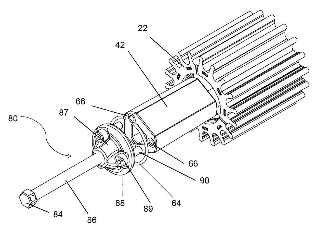
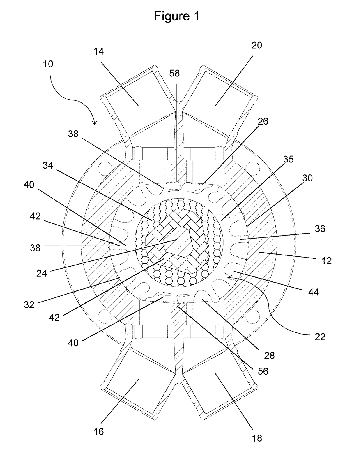
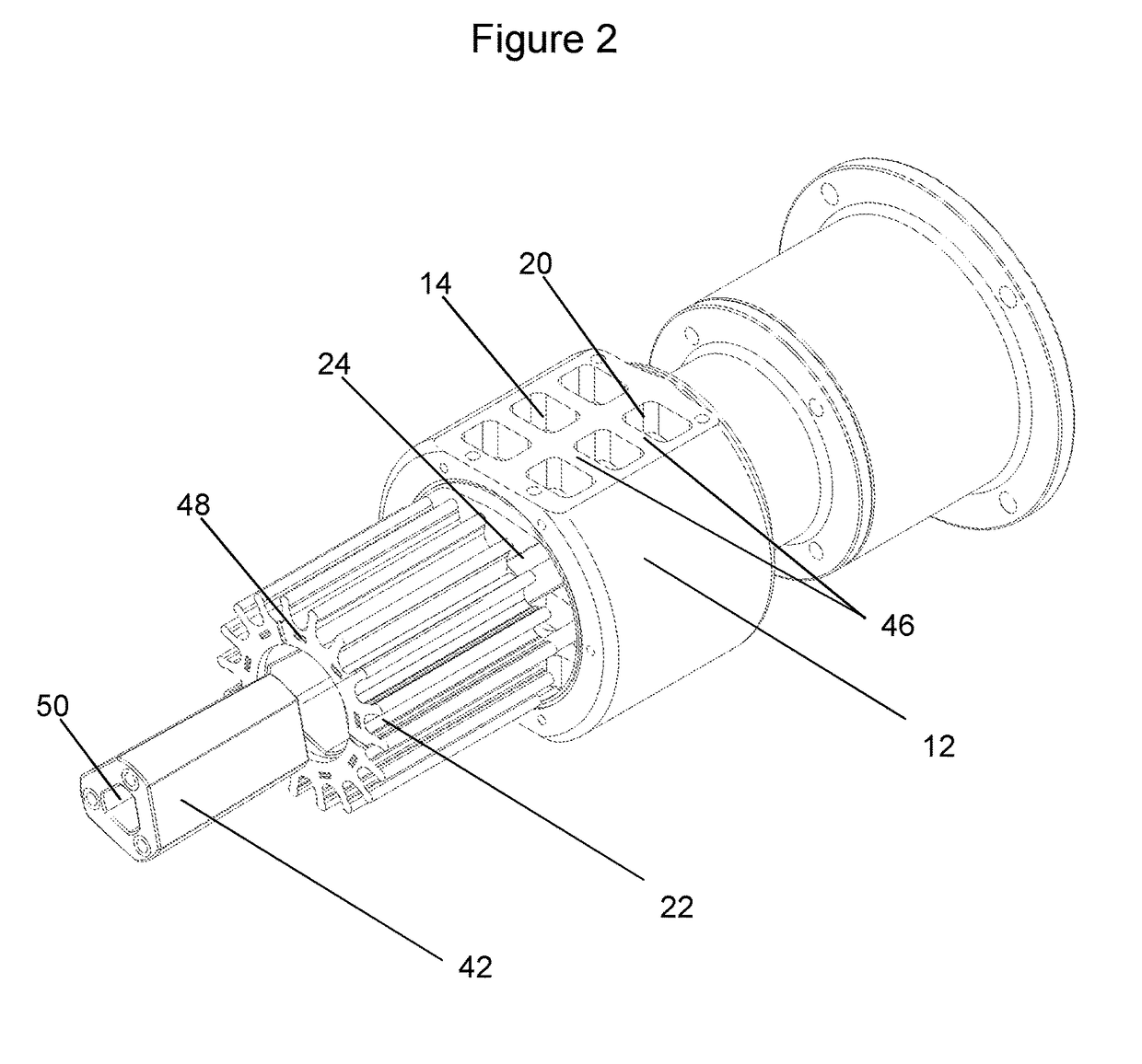
[0093]FIG. 1 shows a dual cam flexible impeller pump 10 according to an exemplary embodiment of the present invention. The flexible impeller pump 10 comprises a pump housing 12, having a first inlet 14, a first outlet 16, and second inlet 18, and a second outlet 20. The pump comprises a flexible impeller 22, which is rotatably mounted in the pump housing 12 on an impeller drive shaft 24.

[0094]The housing comprises cammed surfaces (also referred to as cams) 26 and 28, and cylindrical inner surfaces 30 and 32.

[0095]The impeller 22 comprises a body portion 34,35 from witch a plurality of vanes 36 extend outwards, extending radially when adjacent to the cylindrical surface of the housing, and deflected into a bent configuration when in contact with the cammed surfaces. Each vane comprises a tip 38, a root 40 and a stem 42 extending between the root and this tip. An inter-vane volume 44 is defined by the trough between a vane and the adjacent vane, in which the fluid being pumped is held...


PUM


Abstract

The present invention relates to improvements in the area of flexible impeller pumps. In particular, the present invention relates to flexible impellers with improved profiles(such as dual sealing lips), which are particularly well-suited to multiple cam pumps. A novel mounting hub configuration for mounting an impeller on a drive shaft is also provided. Pumps comprising such impellers and / or mounting hubs are provided, as are associated methods of installation and removal.

Description

FIELD OF THE INVENTION[0001]The present invention relates to flexible impeller pumps. In particular the present invention relates to a flexible impeller having a novel vane configuration, and a pump including such an impeller. In addition the present invention relates to a mounting system for flexible impeller pumps.BACKGROUND TO THE INVENTION[0002]A flexible impeller pump is a well-known form of pump, which combines the priming feature of a positive displacement pump with the fluid transfer ability of a centrifugal pump. A flexible impeller pump is a self-priming pump, which comprises a generally cylindrical housing typically with a single cammed surface, or cam. The housing comprises an inlet and an outlet, both of which are associated with the cam. A flexible impeller having flexible radial vanes is mounted on a rotatable drive shaft; the impeller is typically secured using splines or a key, thus rotationally coupling the impeller to the shaft. The rotating flexible vanes are rec...

Claims


Application Information

Patent Timeline
IPC IPC(8): F04C15/00F04C5/00
CPCF04C15/0076F04C2230/70F04C15/0007F04C5/00F04C2230/604B25B27/023F04C29/0071F04C29/0078F04C15/0073
Inventor DRYSDALE, STUART
Owner MARINE FLOW
Why Eureka
Try Eureka