Heat pump system for vehicle

Active Publication Date: 2017-05-11
HANON SYST
View PDF3 Cites 9 Cited by
  • Summary
  • Abstract
  • Description
  • Claims
  • Application Information

AI Technical Summary

Benefits of technology

The heat pump system for the vehicle described in this patent reduces the size and power consumption of the air-conditioning system by using a water-cooled condenser and controlling the heat exchange between refrigerant and coolant based on the mode of operation. A receiver drier is also included to enhance heating performance by rising the pressure of the refrigerant.

Problems solved by technology

Additionally, for radiant heat of the air-cooled condenser 2 increased in size, the system requires a large-capacity blower 20 and a large-capacity motor, and it causes an increase of power consumption and an increase of noise due to lots of air volume.

Method used


Image

  • Heat pump system for vehicle
  • Heat pump system for vehicle
  • Heat pump system for vehicle

Examples


Embodiment Construction

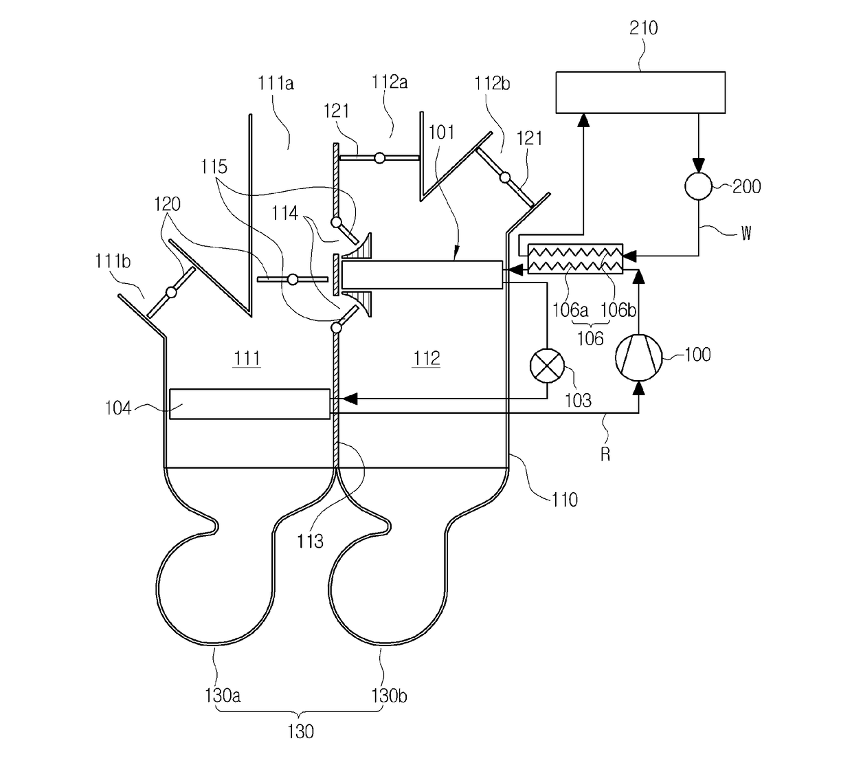
[0036]Reference will be now made in detail to the preferred embodiment of the present invention with reference to the attached drawings.

[0037]As shown in the drawings, a heat pump system for a vehicle according to the present invention includes a compressor 100, an air-cooled condenser 101, expansion means 103 and an evaporator 104 connected with one another through a refrigerant circulation line (R) so as to carry out cooling through the evaporator 104 and carry out heating through the air-cooled condenser 101, and further includes a water-cooled condenser 106.

[0038]First, the compressor 100 inhales and compresses gas-phase refrigerant of low-temperature and low-pressure discharged from the evaporator 104 while operating by receiving a driving force from a power supply, such as an engine or a motor, and then, discharges the refrigerant in a gas phase of high-temperature and high-pressure.

[0039]The air-cooled condenser 101 exchanges heat between the gas-phase refrigerant of high-tem...


PUM


Abstract

Disclosed herein is a heat pump system for a vehicle, which includes a compressor, an air-cooled condenser mounted on a warm air passageway, expansion means and an evaporator mounted on a cold air passageway of an air-conditioning case in order to carry out heating and cooling and further includes a water-cooled condenser mounted on a refrigerant circulation line between the compressor and the air-cooled condenser to exchange heat between refrigerant and coolant, thereby reducing the number and the size of blowers and the size of the entire system because the size of the air-cooled condenser inside the warm air passageway is reduced, and decreasing power consumption and noise by reducing capacity of a motor of the blower.

Description

TECHNICAL FIELD[0001]The present invention relates to a heat pump system for a vehicle, and more particularly, to a heat pump system for a vehicle, which includes a compressor, an air-cooled condenser mounted on a warm air passageway, expansion means and an evaporator mounted on a cold air passageway of an air-conditioning case in order to carry out heating and cooling and further includes a water-cooled condenser mounted on a refrigerant circulation line between the compressor and the air-cooled condenser to exchange heat between refrigerant and coolant.BACKGROUND ART[0002]In general, as shown in FIG. 1, an air conditioner system for a vehicle has a refrigeration cycle that includes: a compressor 1 for compressing and discharging refrigerant; a condenser 2 for condensing the refrigerant of high pressure discharged from the compressor 1; an expansion valve 3 for throttling the refrigerant condensed and liquefied in the condenser 2; and an evaporator 4 for exchanging heat between the...

Claims


Application Information

Patent Timeline
IPC IPC(8): B60H1/00B60H1/32
CPCB60H1/00921B60H1/00064B60H2001/00721B60H2001/00928B60H2001/00135B60H1/3227F25B30/02F25B2339/0441F24F3/052F25B25/005F25B2400/16B60H1/00885F25B2400/0413F25B6/02
Inventor LEE, HAE JUNRYU, JAE CHUNAHN, YONG NAMLEE, SUNG JELEE, SE MIN
Owner HANON SYST
Why Eureka
Try Eureka