Method and apparatus for allocating power levels to a transmission in a digital subscriber line network

a technology of digital subscriber line network and power level, applied in the direction of line-transmission details, power management, high-level techniques, etc., can solve the problem of only reducing the power level of masking frequencies, and achieve the effect of reducing power levels, increasing bandwidth and data rates, and increasing spectrum usag

Active Publication Date: 2017-05-04
BRITISH TELECOMM PLC
View PDF0 Cites 5 Cited by
  • Summary
  • Abstract
  • Description
  • Claims
  • Application Information

AI Technical Summary

Benefits of technology

[0011]Embodiments of the present disclosure may therefore provide a tailor made transmit spectral mask for the subscriber line, by only notching out frequencies used in the RF environment of the line. In this manner, the transmit spectral mask only reduces the power levels for frequencies that have a realistic chance of interfering with other RF services in the location of the subscriber line and its associated network elements. This offers increased usage of spectrum (and thus increased bandwidth and data rates) over the prior art method, which would reduce the power levels for all frequencies on each individual line regardless of whether any RF services are going to be interfered with.
[0012]Furthermore, the method of the present disclosure may construct the transmit spectral mask by identifying a hierarchy of increasingly localized geographic regions associated with the subscriber line and combining the spectral masks tailored to the RF environment of those regions. This allows an entity in the DSL network to effectively layer spectral masks together to create bespoke transmit spectral masks, without the computational complexity of individually calculating the transmit spectral mask for each subscriber line.
[0019]The method of the present disclosure may therefore advantageously reduce the power level to the minimum power level from any one of the spectral masks. This has the additional benefit of still using that part of the spectrum, but without the risk of interfering with other RF services.

Problems solved by technology

In this manner, the transmit spectral mask only reduces the power levels for frequencies that have a realistic chance of interfering with other RF services in the location of the subscriber line and its associated network elements.

Method used


Image

  • Method and apparatus for allocating power levels to a transmission in a digital subscriber line network
  • Method and apparatus for allocating power levels to a transmission in a digital subscriber line network
  • Method and apparatus for allocating power levels to a transmission in a digital subscriber line network

Examples


Embodiment Construction

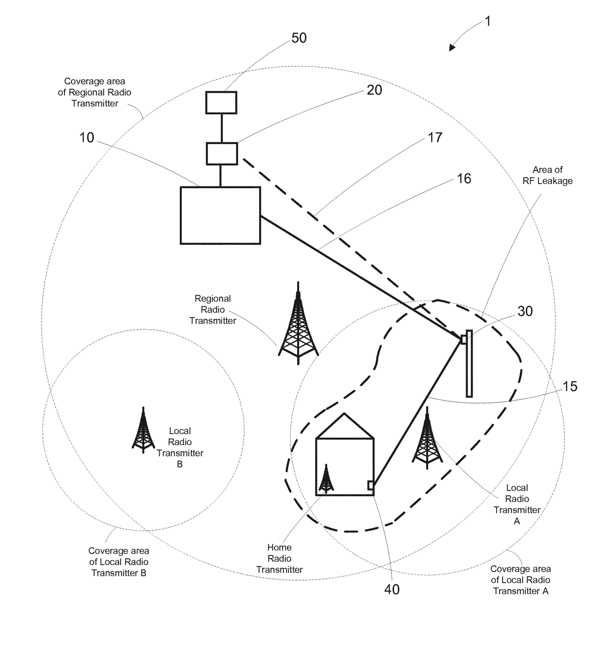
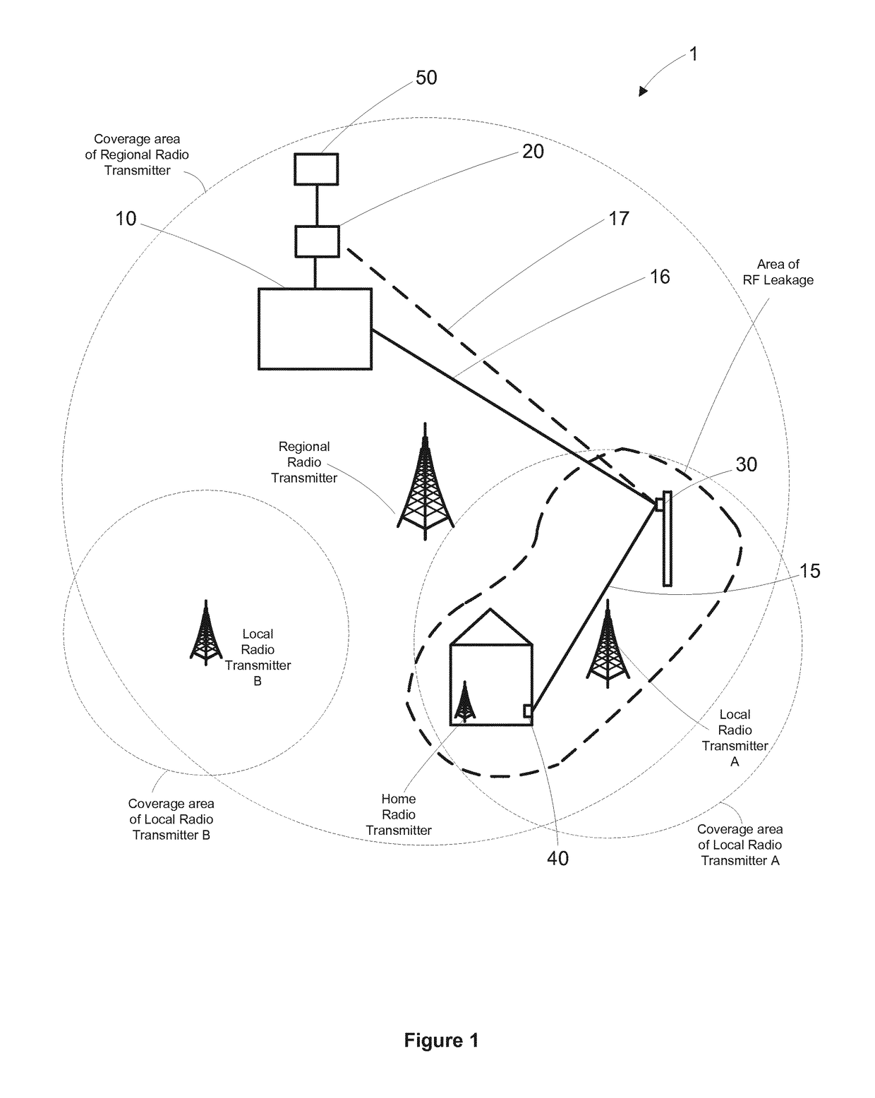
[0033]An embodiment of a Digital Subscriber Line (DSL) network 1 of the present disclosure will now be described with reference to FIGS. 1 to 2. FIG. 1 illustrates an overview of the DSL network 1, which includes an exchange 10, a Persistent Management Entity (PME) 20, a Drop-Point Unit (DPU) 30, and a Customer's Premises Equipment (CPE) 40. The exchange 10, PME 20, DPU 30 and CPE 40 are all connected by a subscriber line, which consists of a fiber part 16 from the exchange 10 to the DPU 30, and a copper part 15 from the DPU 30 to the CPE 40. The skilled person will understand that the exchange 10, PME 20 and DPU 30 would normally have a one-to-many relationship with network elements lower down in the DSL network hierarchy, but a one-to-one mapping is used in this description for simplicity.

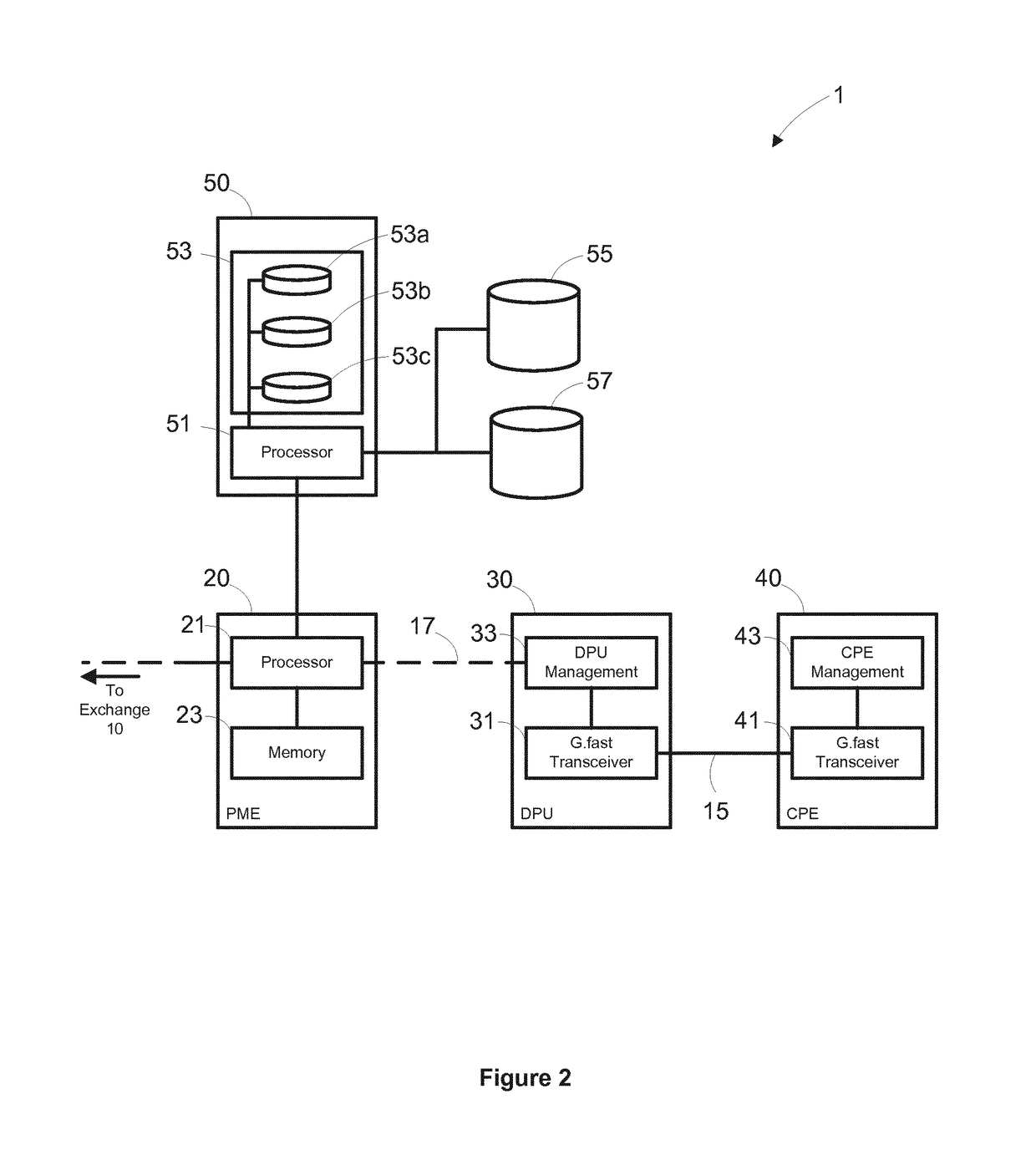
[0034]FIG. 1 also shows a mask constructor 50 connected, in this embodiment, to the PME 20. As shown in more detail in FIG. 2, the mask constructor 50 includes a processor 51, mask database 53 (i...


PUM


Abstract

Embodiments relate to a method, and a device for performing the method, for allocating power levels to a transmission in a DSL network, the method including: identifying a first and second geographical region as being associated with a subscriber line in the DSL network; defining a first spectral mask having a first set of power levels over a range of frequencies, wherein the first set of power levels are tailored according to a Radio Frequency, RF, environment of the first geographical region; defining a second spectral mask having a second set of power levels over the range of frequencies, wherein the second set of power levels are tailored according to an RF environment of the second geographical region; and constructing a transmit spectral mask for the subscriber line, the transmit spectral mask based on a combination of the first and second spectral masks, including, for each frequency in the range of frequencies, using the minimum power level for that frequency from the first and second spectral masks.

Description

CROSS-REFERENCE TO RELATED APPLICATIONS[0001]The present application is a National Phase entry of PCT Application No. PCT / EP2015 / 065248, filed on 3 Jul. 2015, which claims priority to EP Patent Application No. 14179207.7, filed on 30 Jul. 2014, which are hereby fully incorporated herein by reference.TECHNICAL FIELD[0002]The present disclosure relates to a method and apparatus for allocating power levels to a transmission in a DSL network. In particular, this disclosure relates to using spectral masks for allocating power levels over a range of frequencies for a transmission in the DSL network.BACKGROUND[0003]Digital Subscriber Lines (DSL) are a common technology for providing digital communication. In early DSL deployments, a broadband connection to a customer's premises was provided by a DSL connection extending over an existing twisted copper pair subscriber line between two DSL modems located in the exchange (Central Office in US terminology) and the customer's premises respectiv...

Claims


Application Information

Patent Timeline
Patent Type & Authority Applications(United States)
IPC IPC(8): H04M11/06H04M19/00
CPCH04M19/001H04M11/062H04B3/46H04W52/00Y02D30/70
Inventor LINNEY, TREVORHORSLEY, IANMORSMAN, TREVOR
Owner BRITISH TELECOMM PLC
Why Eureka
Try Eureka