
Magnetic resonance imaging matrix shim coil system and method

a magnetic resonance imaging and matrix shim coil technology, applied in the field of magnetic resonance imaging, can solve the problems of reducing the range of geometric shapes which gradient coils can modulate, and reducing the image quality, so as to improve the image quality in the magnetic resonance imaging system and mitigate one or more b0 field orientation deviations

Active Publication Date: 2017-05-04
GENERAL ELECTRIC CO
View PDF1 Cites 2 Cited by
  • Summary
  • Abstract
  • Description
  • Claims
  • Application Information

AI Technical Summary

Benefits of technology

The patent text describes methods for improving image quality and compensating gradient coil alignment in magnetic resonance imaging systems. These methods involve rapidly modulating an electrical current in a matrix shim coil to compensate for high order eddy currents or to mitigate B0 field orientation deviations resulting from the alignment of gradient coils. These techniques can help to improve the accuracy and reliability of magnetic resonance imaging systems.

Problems solved by technology

In turn, the generated eddy currents may produce additional magnetic fields, known as eddy current fields and / or reflective fields, which can distort the B0 field and degrade image quality.
The geometric shapes which gradient coils can modulate is limited, which in turn limits the spatial harmonics order of B0 field inhomogeneities that can be compensated for.

Method used


Image

  • Magnetic resonance imaging matrix shim coil system and method
  • Magnetic resonance imaging matrix shim coil system and method
  • Magnetic resonance imaging matrix shim coil system and method

Examples


Embodiment Construction

[0018]Reference will be made below in detail to exemplary embodiments of the invention, examples of which are illustrated in the accompanying drawings. Wherever possible, the same reference characters used throughout the drawings refer to the same or like parts, without duplicative description.

[0019]As used herein, the terms “substantially,”“generally,” and “about” indicate conditions within reasonably achievable manufacturing and assembly tolerances, relative to ideal desired conditions suitable for achieving the functional purpose of a component or assembly. As used herein, “electrically coupled, “electrically connected” and “electrical communication” means that the referenced elements are directly or indirectly connected such that an electrical current may flow from one to the other. The connection may include a direct conductive connection (i.e., without an intervening capacitive, inductive or active element), an inductive connection, a capacitive connection, and / or any other su...


PUM


Abstract

A method for improving image quality in a magnetic resonance imaging system, the method includes rapidly modulating an electrical current in a matrix shim coil of the magnetic resonance imaging system to compensate high order eddy currents in the system.

Description

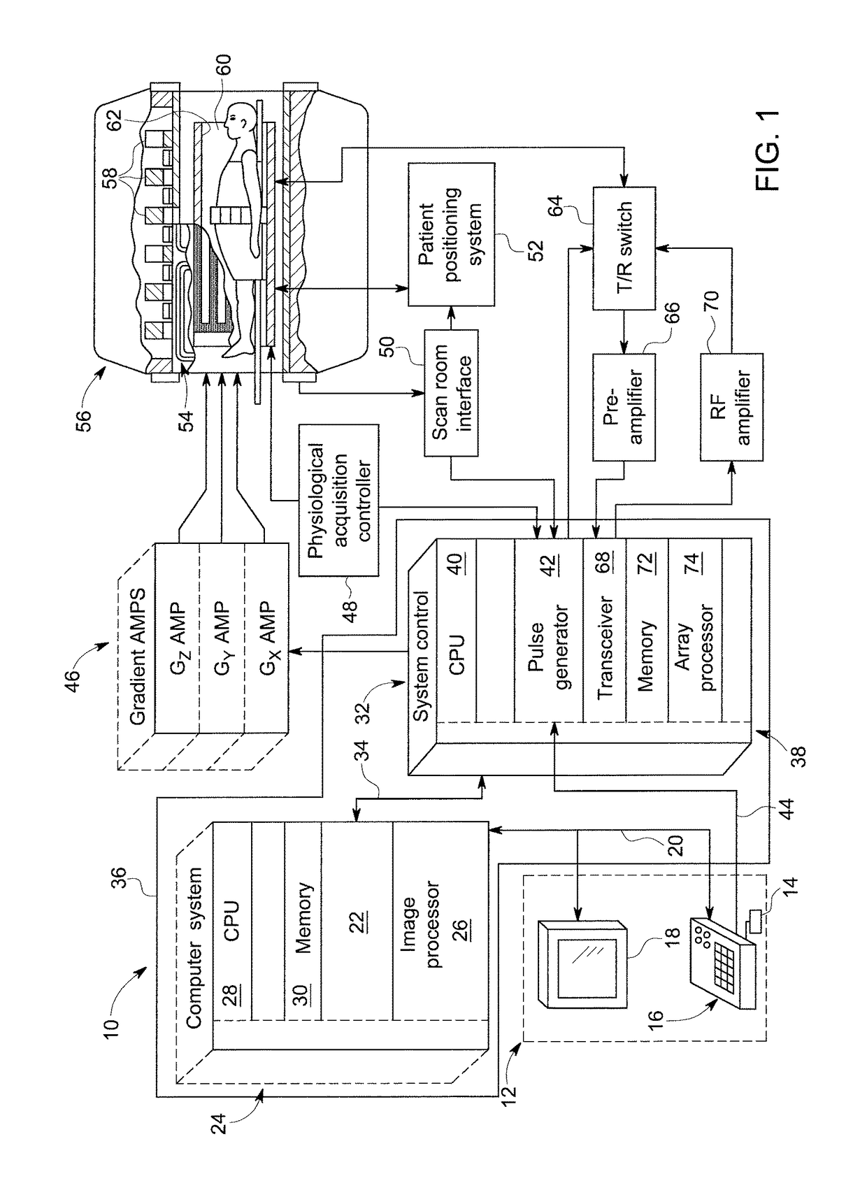
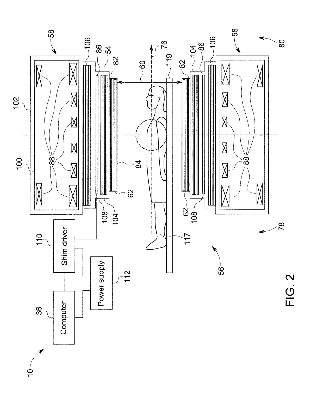
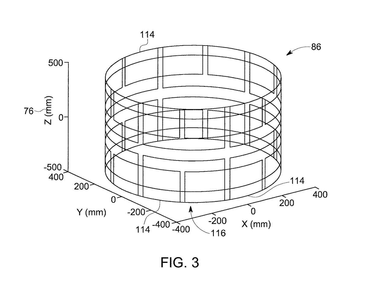
BACKGROUND[0001]Technical Field[0002]Embodiments of the invention relate generally to magnetic resonance imaging (MRI) and, more specifically, to a system and method for using matrix shim coils to generate magnetic fields with low to high order spatial harmonics.[0003]Discussion Of Art[0004]MRI is a widely accepted and commercially available technique for obtaining digitized visual images representing the internal structure of objects having substantial populations of atomic nuclei that are susceptible to nuclear magnetic resonance (NMR). In MRI, imposing a strong main magnetic field (B0) on the nuclei polarizes nuclei in the object to be imaged. The nuclei are excited by a radio frequency (RF) signal at characteristics NMR (Larmor) frequencies. By spatially disturbing localized magnetic fields surrounding the object and analyzing the resulting RF responses from the nuclei as the excited protons relax back to their lower energy normal state, a map or image of these nuclei responses ...

Claims


Application Information

Patent Timeline
Patent Type & Authority Applications(United States)
IPC IPC(8): G01R33/3875G01R33/565
CPCG01R33/3875G01R33/56563G01R33/56518
Inventor MATHIEU, JEAN-BAPTISTESEEBER, DEREK ALLANLEE, SEUNG-KYUN
Owner GENERAL ELECTRIC CO
Learn More