
Door closer assembly with hollow hinge member

Active Publication Date: 2017-05-04
MATECHET KFAR SABA SHAHARBANI BROS 1980
View PDF2 Cites 0 Cited by
  • Summary
  • Abstract
  • Description
  • Claims
  • Application Information

AI Technical Summary

Benefits of technology

The present invention is a door closer assembly that prevents the door from slamming. It has an adjustable brake that safely stops the door from closing too hard. This invention can be used in any kind of door and is especially useful in schools, hospitals, hotels, and office buildings. The door closing is quiet and there will be no annoying sound of the door slamming.

Problems solved by technology

Such door closures are difficult to adjust in that the leakage of the fluid must be adjusted so as to control the speed of operation of the door closing mechanism.

Method used


Image

  • Door closer assembly with hollow hinge member
  • Door closer assembly with hollow hinge member
  • Door closer assembly with hollow hinge member

Examples


Embodiment Construction

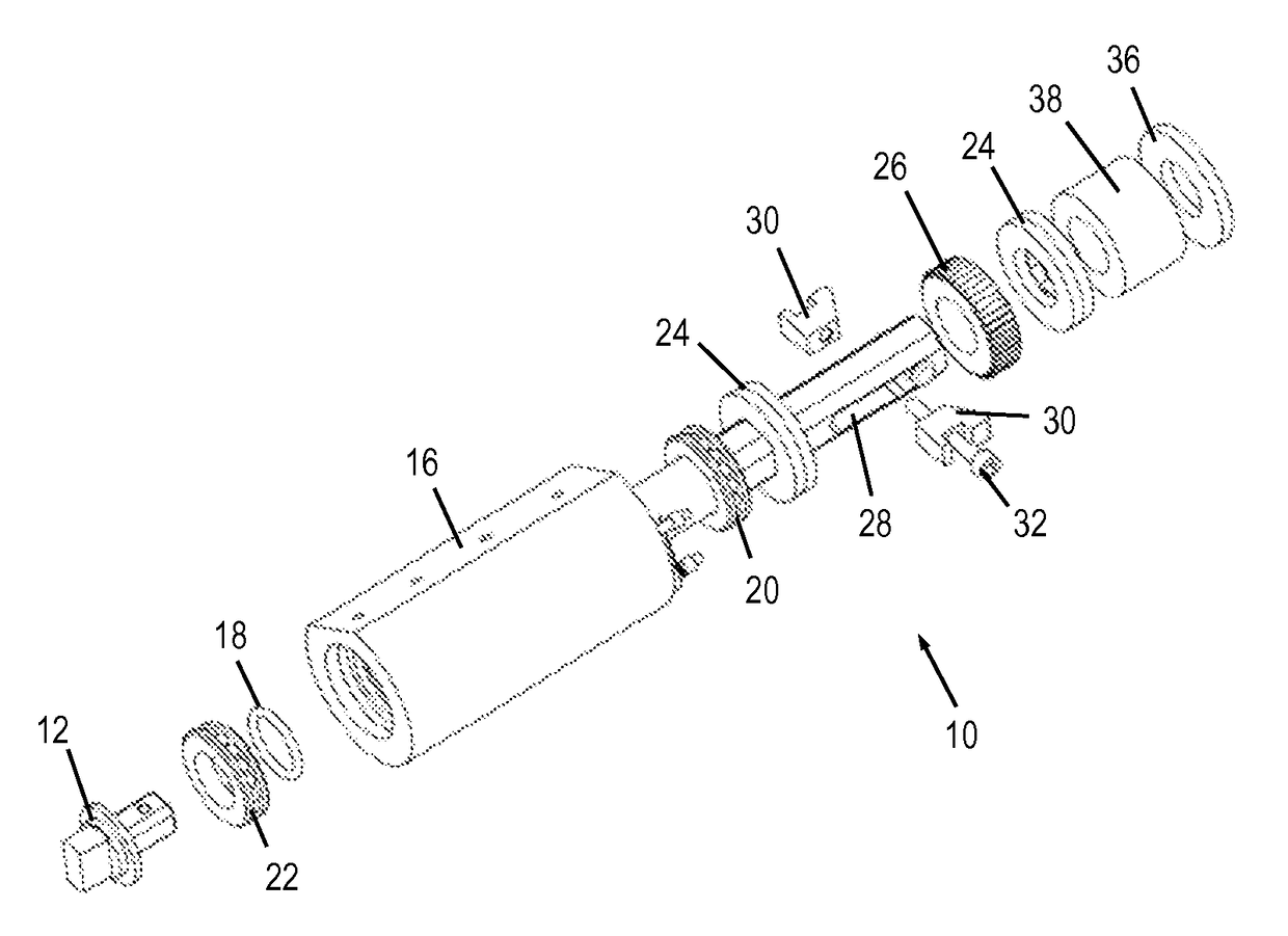
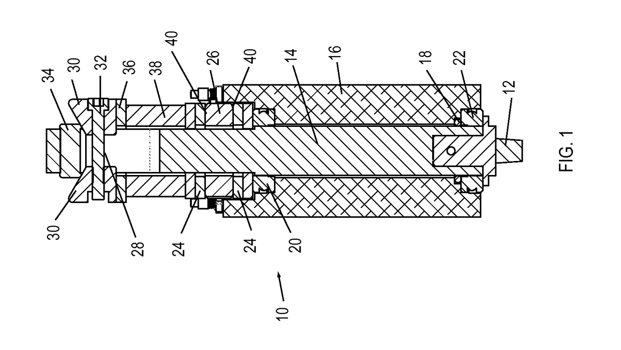
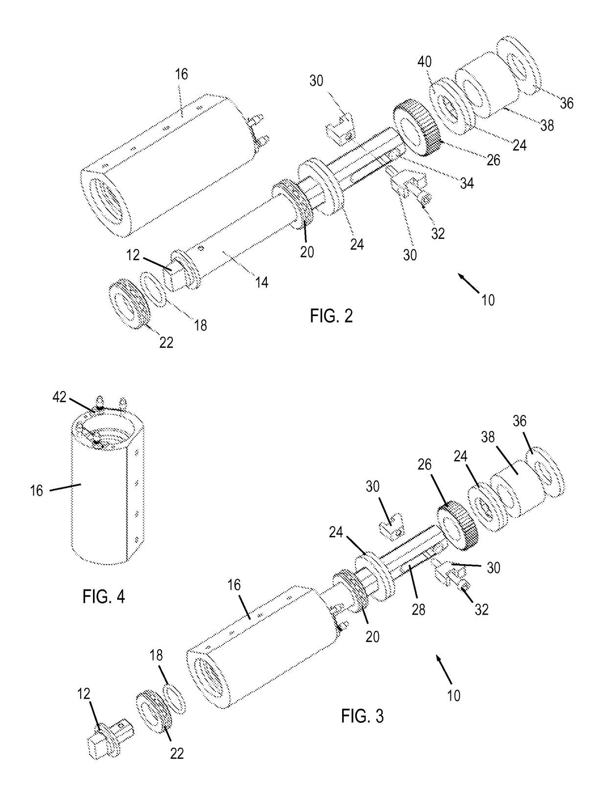
[0019]Reference is now made to FIGS. 1, 2 and 3, which illustrate a door closer assembly 10, constructed and operative in accordance with a non-limiting embodiment of the present invention.

[0020]The door closer assembly 10 includes a lower bushing 12 for mounting in a hinge side of a door (as seen later in FIG. 5). The lower bushing 12 fits into a recess at the bottom end of a central shaft 14. The central shaft 14 is rotatingly mounted in an outer housing 16 and journaled by upper and lower bearings 20 and 22, respectively. An O-ring 18 may seal the shaft 14 above the lower bearing 22.

[0021]Central shaft 14 passes through at least one brake pad 24 and through a ratchet wheel 26. In the illustrated embodiment, there is a pair of brake pads 24, one pad placed below the ratchet wheel 26 and the other pad placed above wheel 26. The upper portion of central shaft 14 is formed with a channel 28. One or more wedges 30 (two are provided in the illustrated embodiment) are slidingly mounted ...


PUM


Abstract

A door closer assembly includes a central shaft rotatingly mounted in an outer housing and which passes through at least one brake pad. One or more wedges are slidingly mounted on the central shaft by means of a fastener. The wedges, upon tightening of the fastener, wedge against an inclined surface, which forces the wedges downwards and applies a downwards force that causes a friction-enhanced surface to rub against the at least one brake pad.

Description

FIELD OF THE INVENTION[0001]The present invention relates generally to door closer assemblies, and more specifically to a door closer assembly that prevents slamming of the door.BACKGROUND OF THE INVENTION[0002]Door closures are known which include a cylinder and piston with a fluid such as air or oil and wherein during door opening or closing, the piston compresses the fluid so as to prevent a door from slamming. Such door closures are difficult to adjust in that the leakage of the fluid must be adjusted so as to control the speed of operation of the door closing mechanism.SUMMARY OF THE INVENTION[0003]The present invention seeks to provide a door closer assembly that prevents slamming of the door, as is described more in detail hereinbelow.[0004]The door closer assembly of the present invention has an adjustable brake that safely brakes closing of the door to prevent slamming. The door closer of the invention, when installed in the hinge side of a door, provides a highly safe door...

Claims


Application Information

Patent Timeline
IPC IPC(8): E05D11/08E06B3/34E05F5/02
CPCE05D11/082E05D2011/085E06B3/34E05F5/02E05F3/16E05F3/20
Inventor SHAHARBANY, RONEN
Owner MATECHET KFAR SABA SHAHARBANI BROS 1980
Learn More