
Coil spring

a coil spring and spring technology, applied in the field of coil springs, can solve the problems of degradation of durability and affect durability, and achieve the effect of improving durability and reducing stress

Inactive Publication Date: 2017-04-20
AISIN AW CO LTD
View PDF0 Cites 6 Cited by
  • Summary
  • Abstract
  • Description
  • Claims
  • Application Information

AI Technical Summary

Benefits of technology

This patent describes a coil spring with a wire that has a cross sectional area increased to increase durability against shearing stress generated during extension and contraction of the coil spring. The wire has a cross sectional shape that includes an outer diameter side part with a circumscribed circle, arc shapes, and linear shapes. The inner diameter side part is semi-elliptical in shape and connected to the linear shapes of the outer diameter side part, resulting in minimal curvature changes and reducing shearing stress concentration. This cross sectional design improves the durability of the coil spring by distributing shearing stress and increasing the cross sectional area.

Problems solved by technology

In addition, when the cross sectional shape of the wire is rectangular to simply increase the cross sectional area, the shearing stress or twisted stress generated by extension and contraction of the coil spring concentrates on corners and fatigue cracks are generated earlier, thereby resulting in degradation of durability.
The contact part of the wire with the above cover receives the stress generated by the centrifugal force and the shearing stress generated by extension and contraction of the coil spring, so the durability may be affected.

Method used


Image

  • Coil spring
  • Coil spring
  • Coil spring

Examples


first embodiment

[0023]The first embodiment will be described with reference to FIG. 1 to FIG. 7.

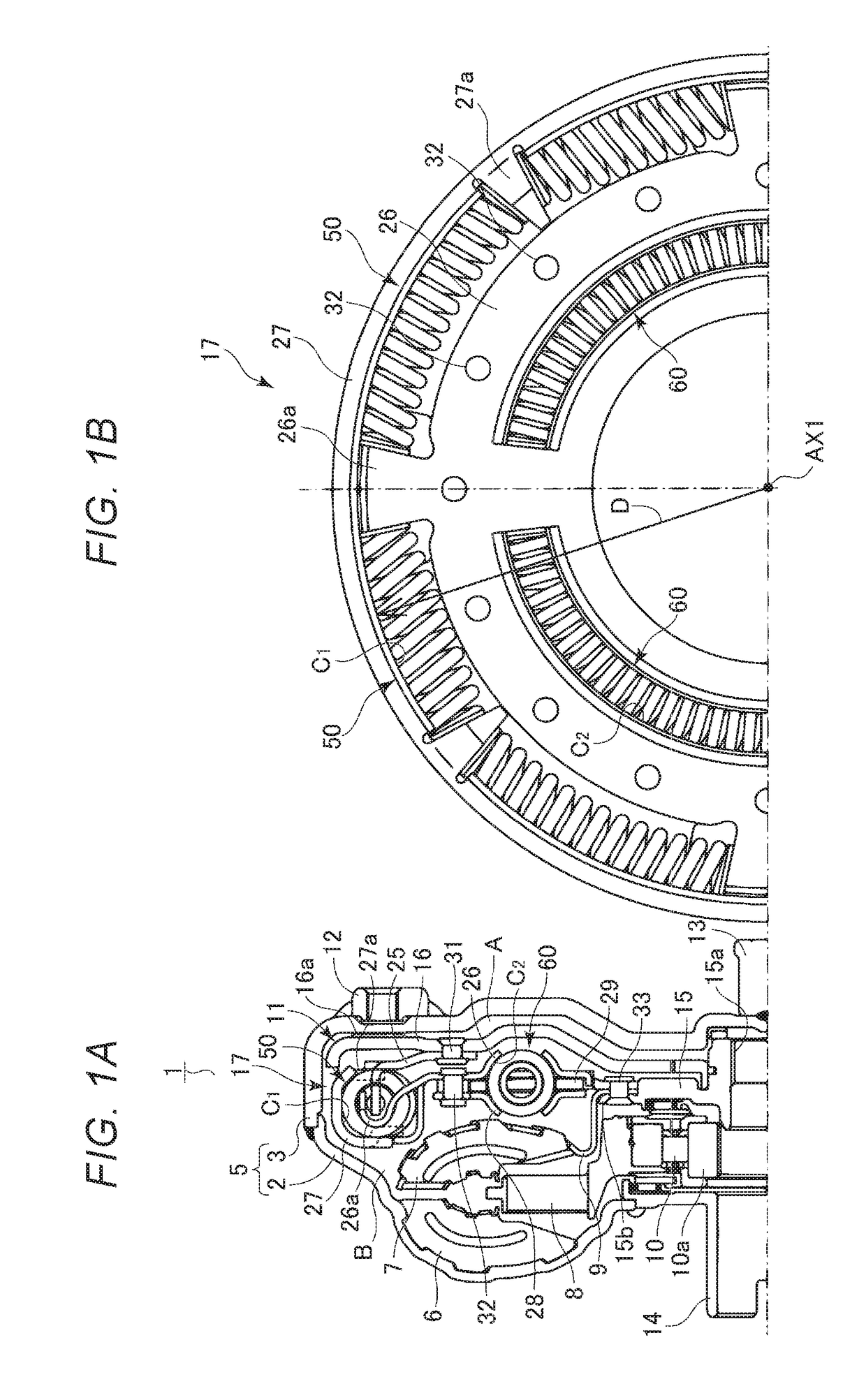
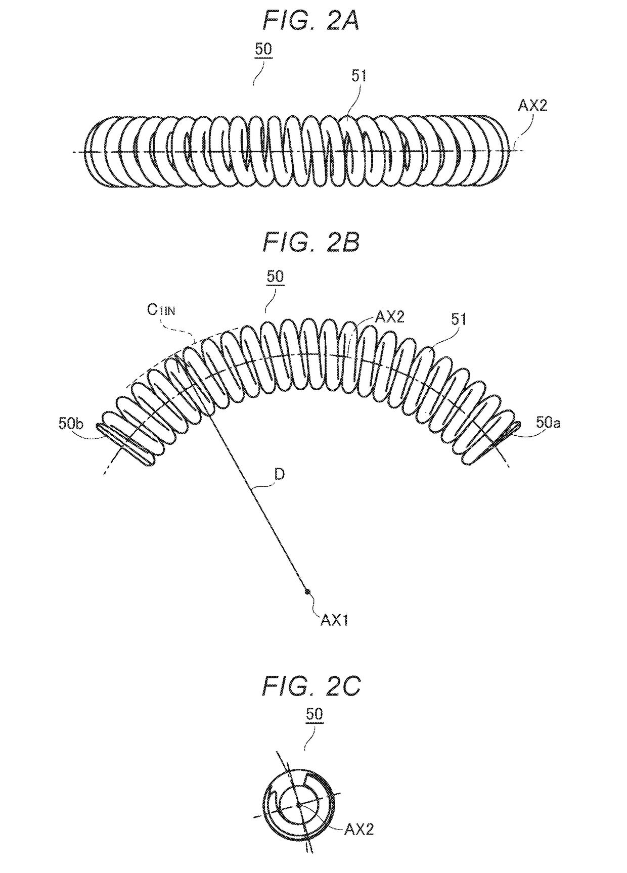
[0024]First, the structure of a torque converter 1 of an automatic transmission to which a coil spring 50 according to the first embodiment is applicable and the structure of a damper portion 17 incorporated therein will be described with reference to FIG. 1.

[0025]As illustrated in FIG. 1A and FIG. 1B, the torque converter 1 has a housing 5 to which a rear cover 2 and a front cover 3 are integrally welded, and the housing 5 accommodates a pump impeller 6, a turbine runner 7, a stator 8, and a lock-up clutch 11. The pump impeller 6 includes many blades fixed to the rear cover 2, the turbine runner 7 includes many blades fixed to an outer hull plate 9, and the stator 8 includes many blades placed on a one-way clutch 10.

[0026]A center piece 13 is anchored to the center of the front cover 3, a set block 12 is anchored to the periphery portion of the front cover 3, the above center piece 13 is fitted to an en...

second embodiment

[0080]Next, the second embodiment obtained by partially changing the first embodiment above will be described with reference to FIG. 8. In the description of the second embodiment, the same components as in the first embodiment are given the same reference numerals to omit the descriptions.

[0081]In the second embodiment, the cross sectional shape of the wire of the coil spring 50 in the first embodiment is changed. Specifically, as illustrated in FIG. 8, the cross sectional shape of a wire 151 includes a semi-elliptical portion 151a, linear portions 151b, arc portions 151d, and a curved portion 151c similarly. Of these components, the shapes of the semi-elliptical portion 151a, the linear portions 151b, and the arc portions 151d are similar to those in the first embodiment.

[0082]The curved portion 151c according to the second embodiment circumscribes, via two points, a circumscribed circle 151out having the radius c about the center point P2 disposed in the center line extending in ...


PUM


Abstract

A coil spring is formed by winding a wire in a coil shape. In the cross sectional shape of the wire formed in the coil shape, the inner diameter side part in the coil shape includes a semi-elliptical shape having a major radius and a minor radius and the outer diameter side part in the coil shape includes a curved shape circumscribing a circumscribed circle having a radius larger than the minor radius, arc shapes having a curvature larger than the curvature of the circumscribed circle, and linear shapes connecting both ends of the arc shapes to both ends of the semi-elliptical shape. This can increase the cross sectional shape of the wire, reduce a shearing stress, and improve the durability of the coil spring.

Description

TECHNICAL FIELD[0001]This technique relates to a coil spring used in a damper device of a transmission or the like mounted in, for example, a vehicle.BACKGROUND ART[0002]Generally, an automatic transmission or manual transmission mounted in a vehicle or the like is provided with a damper device for absorbing vibrations transferred from an internal combustion engine and transferring rotation to a transmission mechanism. The damper device generally includes a drive plate, a driven plate, and a coil spring present therebetween. The coil spring provided in the damper device is manufactured by winding one wire in a coil shape. The general basic shape of the cross section of the wire is a circle as a simple shape or an egg shape obtained by combining a semi-elliptical shape having, for example, a major radius a and a minor radius b with a semicircle having a radius b (see Patent Document 1).[0003]By the way, when the wire is thicken (that is, the wire has a large cross sectional area), th...

Claims


Application Information

Patent Timeline
Patent Type & Authority Applications(United States)
IPC IPC(8): F16F1/06F16F1/02
CPCF16F1/06F16F1/028F16D3/12F16H45/02F16H2045/0221F16F2238/026F16F1/047F16F15/134
Inventor TAKIKAWA, YOSHIHIROWATANABE, YASUHIRO
Owner AISIN AW CO LTD
Learn More