
Control and electrical connections for electrode endocutter device

a technology of electrical connection and electrode, applied in the field of medical devices, can solve problems such as the challenge of controlling bleeding

Active Publication Date: 2017-04-20
CILAG GMBH INT
View PDF11 Cites 74 Cited by
  • Summary
  • Abstract
  • Description
  • Claims
  • Application Information

AI Technical Summary

Benefits of technology

The patent text describes a power and control assembly for a surgical device that includes a housing structure that is attached to the surgical device around its shaft. The housing structure includes a first wire and a second wire that are both coupled to a power source. The first wire is further electrically coupled to the shaft, and the second wire is further electrically coupled to the wiping electrode coagulation system. The housing structure is detachable from the shaft and provides power to the wiping electrode coagulation system. The power and control assembly is designed to control the use of the wiping electrode coagulation system during surgery.

Problems solved by technology

When performing certain surgical procedures, there is a challenge to control bleeding and provide sealing of smaller vessels of tissue at the surgical site.
When parenchyma is separated, there is a challenge to prevent bleeding, seal small (1-2 mm) bile ducts as well as larger 9+ mm vessels.
There is also a challenge to isolate critical ducts and vessels without damaging them.

Method used


Image

  • Control and electrical connections for electrode endocutter device
  • Control and electrical connections for electrode endocutter device
  • Control and electrical connections for electrode endocutter device

Examples


Embodiment Construction

[0067]In the following detailed description, reference is made to the accompanying drawings, which form a part hereof. In the drawings, similar symbols and reference characters typically identify similar components throughout the several views, unless context dictates otherwise. The illustrative embodiments described in the detailed description, drawings, and claims are not meant to be limiting. Other embodiments may be utilized, and other changes may be made, without departing from the scope of the subject matter presented here.

[0068]The following description of certain examples of the technology should not be used to limit its scope. Other examples, features, aspects, embodiments, and advantages of the technology will become apparent to those skilled in the art from the following description, which is by way of illustration, one of the best modes contemplated for carrying out the technology. As will be realized, the technology described herein is capable of other different and obv...


PUM


Abstract

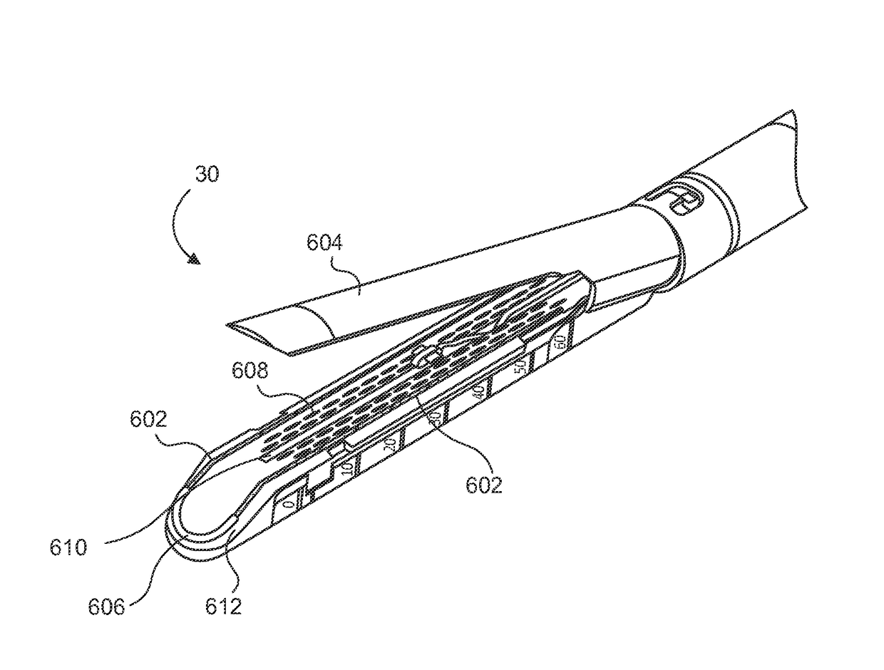
Aspects of the present disclosure include an attachable power and control system to supply energy to electrodes of a wiping electrode coagulation system of a surgical device. A surgical device includes electrodes at an end of effector to aide in sealing during various surgical procedures. During the procedure, the surgeon may wipe the surgical site with the end effector, causing the electrodes to touch the fractured area. Electrosurgical energy may be applied to the electrodes during the wiping, causing coagulation of smaller vessels. The attachable power and control system may be configured to slide over the shaft of the surgical device. The power and control system also may be configured to supply power to the electrodes and to control when energy is applied to the electrodes, based in part, for example, on measuring a distance or angle of the opening of the jaws at the end effector.

Description

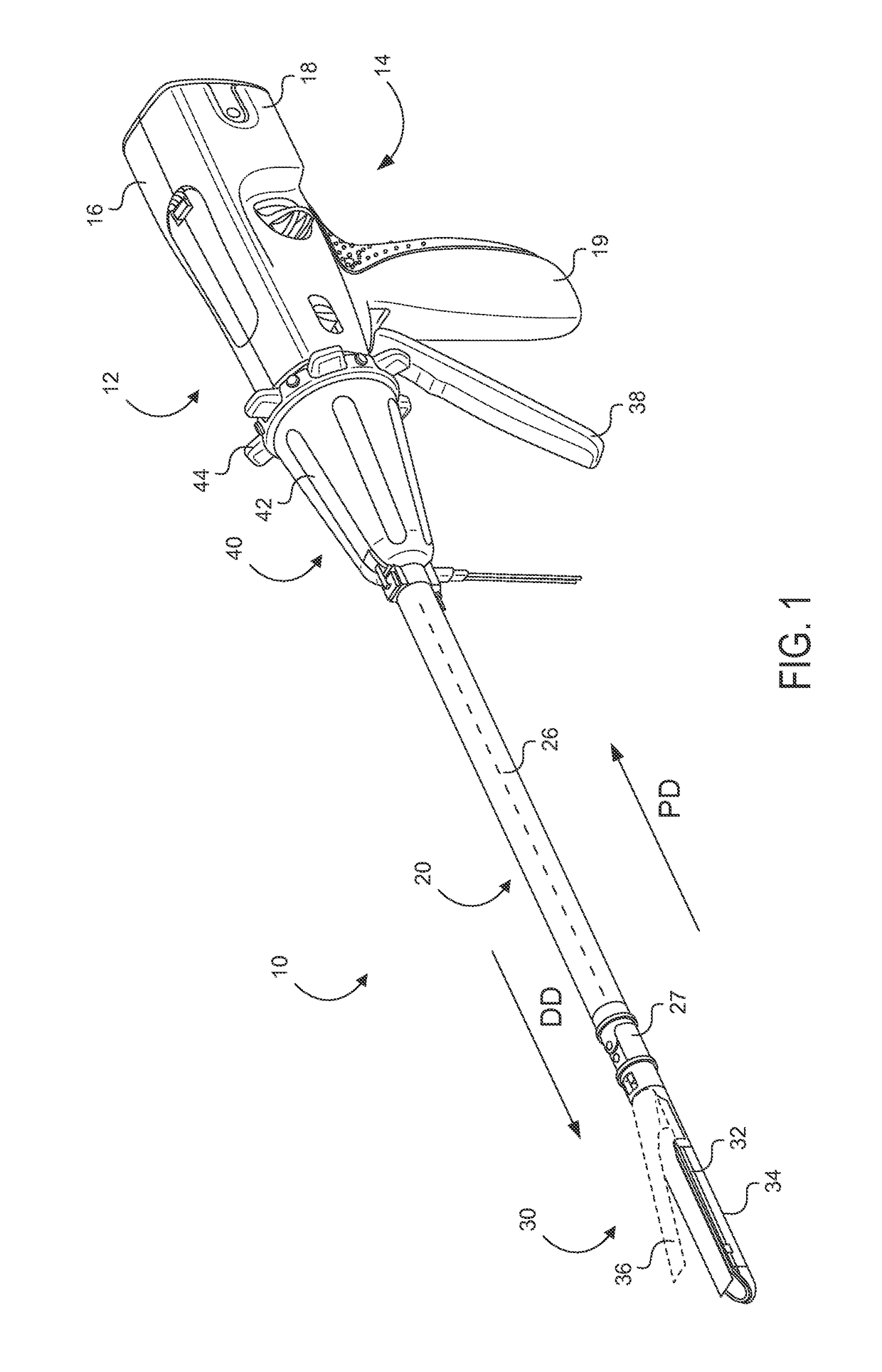
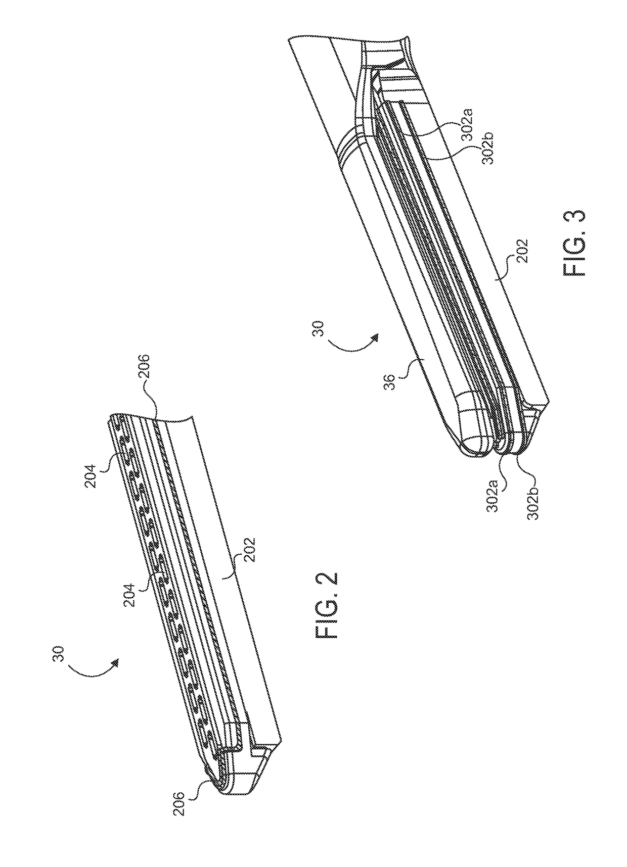
CROSS REFERENCE TO RELATED APPLICATION[0001]This application is related to US non-provisional application Ser. No. ______, Attorney Docket Number END7882USSNP / 150588, filed concurrently herewith, and titled “ELECTRODE WIPING SURGICAL DEVICE,” the entire disclosure of which is hereby incorporated by reference in its entirety and for all purposes.TECHNICAL FIELD[0002]The present disclosure is related generally to medical devices with various mechanisms for cutting and sealing tissue. In particular, the present disclosure is related to power and control apparatuses for medical devices with stapling and cutting instruments having electrodes positioned at the end effector for sealing in a wiping motion, suitably for performing surgical procedures on the liver.BACKGROUND[0003]When performing certain surgical procedures, there is a challenge to control bleeding and provide sealing of smaller vessels of tissue at the surgical site. For example, in a liver resection, also referred to as a he...

Claims


Application Information

Patent Timeline
IPC IPC(8): A61B18/12A61B18/14
CPCA61B18/1206A61B18/1445A61B2018/1495A61B2018/00988A61B2018/00642A61B2018/00702A61B2018/1452A61B2018/00178A61B2018/00184A61B2018/00529A61B2018/00404A61B17/068A61B2018/00589A61B18/12A61B18/1233A61B2018/00922A61B2090/067A61B2090/061
Inventor SCHEIB, CHARLES J.ZEINER, MARK S.YATES, DAVID C.
Owner CILAG GMBH INT
Learn More