
Image forming apparatus

a technology of forming apparatus and toner, which is applied in the direction of electrographic process apparatus, instruments, optics, etc., can solve the problems of image defect not being completely collected in the developing device, image defect caused, and part of the toner is excessively charged to the normal polarity at the charging process portion, so as to suppress drum fusion and image defect, stable charge amount

Active Publication Date: 2017-04-06
CANON KK
View PDF0 Cites 2 Cited by
  • Summary
  • Abstract
  • Description
  • Claims
  • Application Information

AI Technical Summary

Benefits of technology

The present invention aims to provide an image forming apparatus that can prevent drum fusion and image defects while maintaining a stable charge amount. This is achieved by controlling the charge polarity of transfer residual toner so that it remains normal. Overall, the invention helps to prolong the life of the apparatus and improve image quality.

Problems solved by technology

Incidentally, in the conventional image forming apparatus using the cleaner-less system, the transfer residual toner remains on the photosensitive drum without being completely collected in the developing device and thus an image defect is caused in some cases.
However, in the image forming apparatus using the cleaner-less system as disclosed in JP-A 2004-54142, there was a problem such that the transfer residual toner was fused on the photosensitive drum and caused image defect without being completely collected in the developing device.
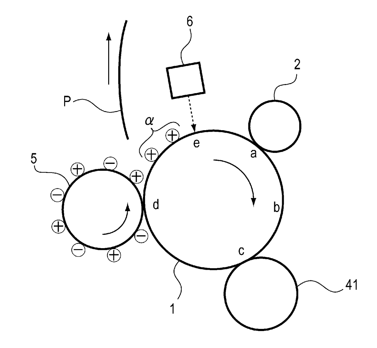
For example, when the toner charged to the normal polarity by cleaning of the transfer member during non-image formation is moved on the photosensitive drum, a part of this toner is excessively charged to the normal polarity at a charging process portion.
As a result, there was a problem that the transfer residual toner could not be collected by the developing device and then during subsequent image formation, image defect such that the toner passed through the developing portion was placed on an image generated.
Or, there was a problem that the drum fusion portion caused excessive electric discharge by an excessively low electric resistance during the charging process and thus a white void (a portion where a dot-shaped toner was not deposited) was formed in the unintended region generated.

Method used


Image

  • Image forming apparatus
  • Image forming apparatus
  • Image forming apparatus

Examples


embodiment 1

IMAGE FORMING APPARATUS

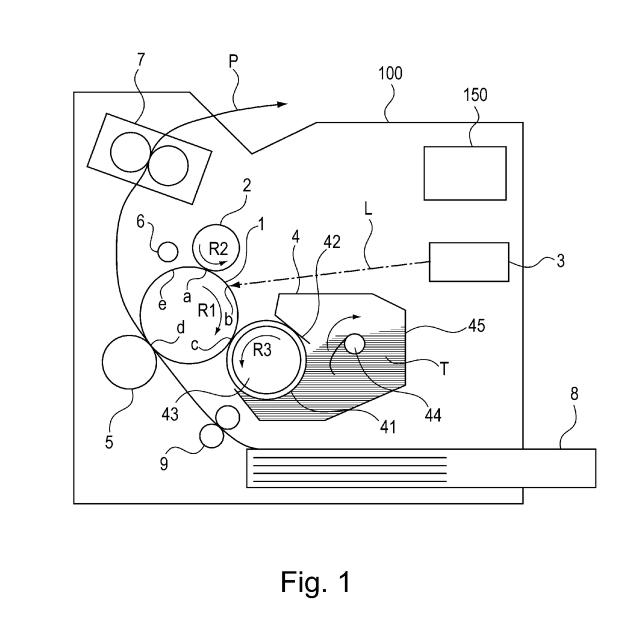
[0021]FIG. 1 is a schematic structural view of an image forming apparatus 100 in Embodiment 1 of the present invention. In this embodiment, the image forming apparatus 100 is illustrated as a laser beam printer of an electrophotographic type employing a cleaner-less system and a contact charging type.

[0022]As shown in FIG. 1, the image forming apparatus 100 includes a photosensitive drum 1 which is a drum-shaped (cylindrical) electrophotographic photosensitive member as a rotatable image bearing member. When an image outputting operation is started, the photosensitive drum 1 is rotationally driven by an unshown driving motor in an arrow R1 direction indicated in FIG. 1. A surface of the rotating photosensitive drum 1 is electrically charged uniformly to a predetermined polarity (negative (polarity) in this embodiment) and a predetermined potential by a charging roller which is a roller-shaped charging member as a charging means. The charging roller 2 is provid...

modified embodiment 1

[0072]A modified embodiment of Embodiment 1 described above will be described. In Embodiment 1, the cleaning operation of the transfer roller 5 was executed in the post-rotation step performed during non-image formation. On the other hand, in this Modified Embodiment 1, in an image forming apparatus 100 having the same constitution as in Embodiment 1, the cleaning operation is executed in a pre-rotation step performed during non-image formation. In the constitution of the image forming apparatus 100 used in this Modified Embodiment 1, members (portions) identical to those in Embodiment 1 are represented by the same reference numerals or symbols and will be omitted from description.

[0073]In this modified embodiment, as the transfer bias, the following 3 biases “HIGH1”, “HIGH2” and “LOW” are used.

[0074]HIGH1: ATVC set bias . . . about +1000 V

[0075]HIGH2: Image leading end bias . . . +1100 V

[0076]LOW: Cleaning bias . . . -1100 V

6>

[0077]FIG. 13 shows a timing chart of the cleaning opera...

embodiment 2

[0094]An image forming apparatus according to Embodiment 2 will be described. The image forming apparatus 100 in this embodiment is not provided with the pre-exposure device 6 as in Embodiment 1, but the charging bias is made variable depending on the polarity of the toner transferred from the transfer roller 5 onto the photosensitive drum 1, so that stable negative electric charges are imparted to the toner after passed through the charging portion a. In the constitution of the image forming apparatus 100 used in this embodiment, members (portions) identical to those in Embodiment 1 are represented by the same reference numerals or symbols and will be omitted from description.

[0095]In this embodiment, as the transfer bias, the following 3 biases “HIGH”, “LOW1” and “LOW2” are used.

[0096]HIGH: Image trailing end bias . . . +1000 V

[0097]LOW1: Cleaning bias . . . +200 V

[0098]LOW2: Cleaning bias . . . −1200 V

[0099]FIG. 14 shows a timing chart of the cleaning operation of the transfer ro...


PUM


Abstract

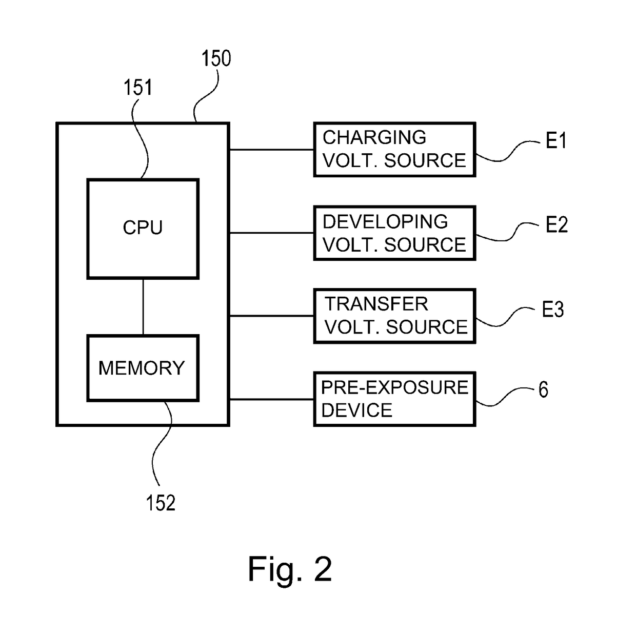
An image forming apparatus includes a discharging device for discharging the drum at a discharging portion opposing the surface of the drum; and a control unit for executing, during non-image formation, a cleaning operation for transferring the toner deposited on the transfer member onto the drum by applying a voltage from transfer voltage source to the transfer member. The control unit does not effect discharge by the discharging device for at least a region of the drum where a transfer voltage for transferring a normal-polarity toner of the toner deposited on the transfer member onto the drum is applied to the transfer member in the cleaning operation, and then passes the region of the drum through the charging portion in a state in which a voltage larger than a surface potential of the drum in a normal polarity side is applied to the charging member.

Description

FIELD OF THE INVENTION AND RELATED ART[0001]The present invention relates to an image forming apparatus, such as a laser printer, a copying machine or a facsimile machine, using an electrophotographic recording type.[0002]In a conventional image forming apparatus of the electrophotographic type, a photosensitive drum as an image bearing member is electrically charged uniformly, and thereafter exposure to light in accordance with an image pattern is made, so that an electrostatic latent image is formed on the photosensitive drum. Thereafter, the electrostatic latent image formed on the photosensitive drum is developed and visualized with a toner, and thereafter a resultant toner image is transferred onto a recording material such as paper. Then, a transfer residual toner remaining on the photosensitive drum is removed from the photosensitive drum and is collected.[0003]As a means for removing and collecting the transfer residual toner from the photosensitive drum, a cleaning device i...

Claims


Application Information

Patent Timeline
IPC IPC(8): G03G15/16
CPCG03G15/161G03G15/00G03G15/1645G03G15/168G03G21/0064G03G21/06G03G21/08G03G15/0266G03G15/0258G03G21/0047
Inventor KOBAYASHI, SHINSUKEAKAMATSU, TAKAAKISHINDO, KENJIOKAYASU, KOHEISASAME, HIROKI
Owner CANON KK
Learn More