
Display device

a technology of display device and bezel area, which is applied in the field of display device, can solve the problems of limiting the implementation of various beautiful appearances and increasing the size of the bezel area

Active Publication Date: 2017-03-23
LG DISPLAY CO LTD
View PDF5 Cites 17 Cited by
  • Summary
  • Abstract
  • Description
  • Claims
  • Application Information

AI Technical Summary

Benefits of technology

The invention aims to create a display that has a smaller bezel area and no sudden changes in the shape of the bezel. This makes the display look better and more consistent.

Problems solved by technology

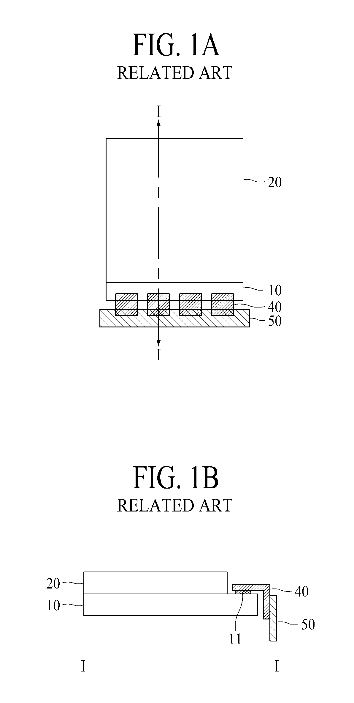
Such a display device according to the related art may have disadvantages in that the size of a bezel area increases as the top faces of the signal pads 11 are exposed for an electrical connection to the flexible printed circuit film 40.
Also, stepped portions may be present in the bezel area, which may limit implementation of various beautiful appearances.

Method used


Image

  • Display device
  • Display device
  • Display device

Examples


Embodiment Construction

[0047]Advantages and features of the invention and methods for achieving the advantages or features will be apparent from embodiments described below in detail with reference to the accompanying drawings. However, the invention is not limited to the embodiments but can be modified in various forms. The embodiments are provided merely for completing the disclosure of the invention and are provided for completely informing those skilled in the art of the scope of the invention. The scope of the invention is defined by only the appended claims.

[0048]Shapes, sizes, ratios, angles, number of pieces, and the like illustrated in the drawings, which are provided for the purpose of explaining the embodiments of the invention, are exemplary and thus the invention is not limited to the illustrated details. In the following description, like elements are referenced by like reference numerals. When it is determined that detailed description of the relevant known functions or configurations invol...


PUM

PropertyMeasurementUnit
area DAaaaaaaaaaa
flexibleaaaaaaaaaa
connection structureaaaaaaaaaa

Abstract

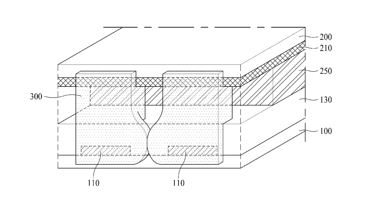
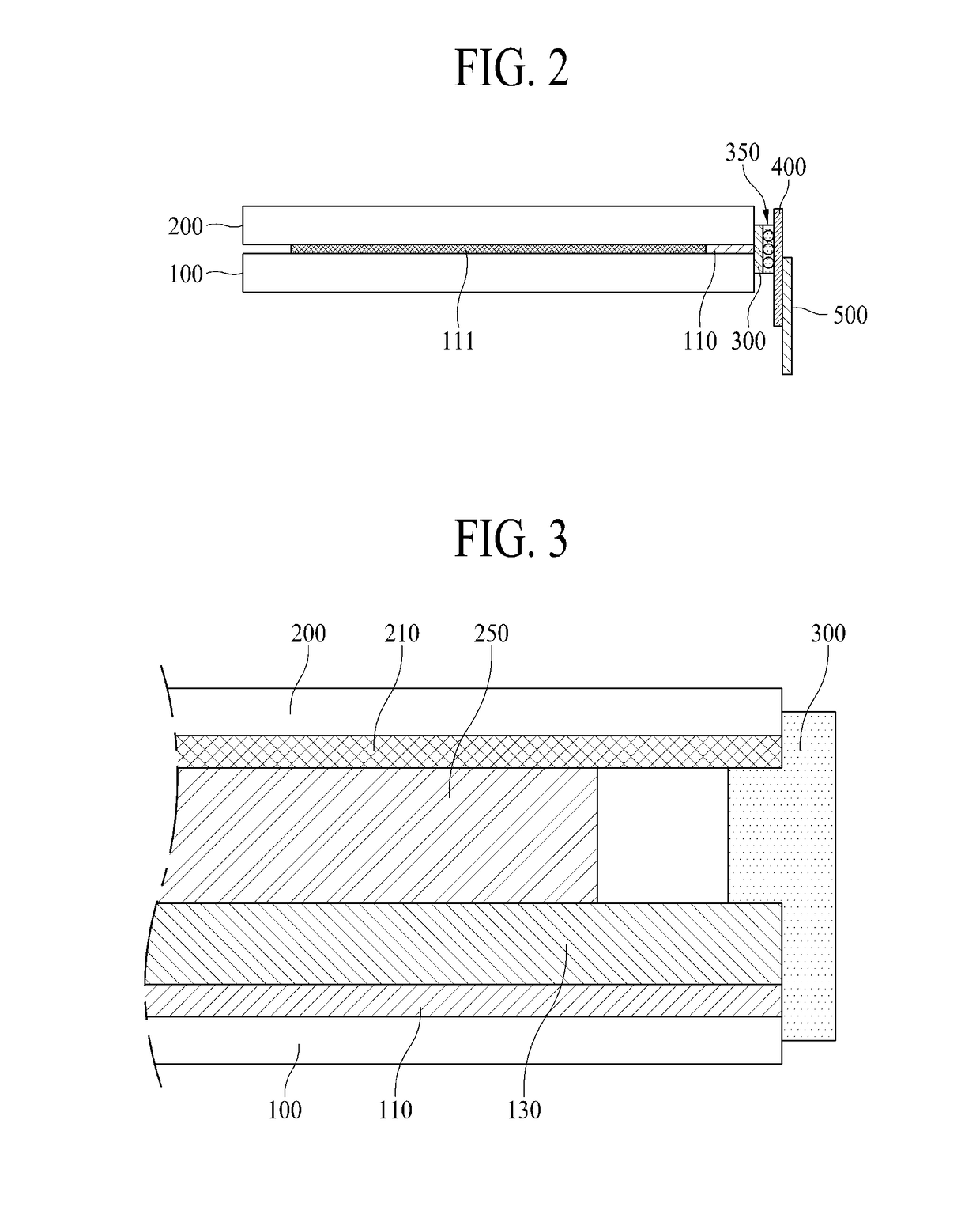
A display panel according to various embodiments comprises: a first substrate and a second substrate facing each other; a first pad and a second pad between the first substrate and the second substrate at an end of the first substrate; a first connection electrode on a side face of the first pad and a second connection electrode on a side face of the second pad; an insulating layer disposed on a top face of the first substrate and disposed on at least a portion of a top face of the first and second pads; and at least one spread prevention hole in the insulating layer between the first and second pads.

Description

CROSS REFERENCE TO RELATED APPLICATIONS[0001]This application claims the benefit of Korean Patent Application No. 10-2015-0132557 filed on Sep. 18, 2015, which is hereby incorporated by reference in its entirety.BACKGROUND[0002]Field of the Disclosure[0003]The present invention relates to a display device and a method for manufacturing the same, and more particularly, to a display device having a structure for connecting a panel driver to a display panel.[0004]Discussion of the Related Art[0005]Display devices such as a liquid crystal display device, a plasma display panel device, and an organic light emitting display device have been developed.[0006]A display device includes a display panel for displaying an image and a panel driver for driving the display panel. A connection structure of the display panel and the panel driver according to the related art will be described below with reference to the accompanying drawings.[0007]FIG. 1A is a schematic plan view of a display device a...

Claims


Application Information

Patent Timeline
Patent Type & Authority Applications(United States)
IPC IPC(8): G02F1/1345G02F1/1335G02F1/1343G02F1/1333G02F1/1339
CPCG02F1/13458G02F1/133345G02F1/1339G02F2202/16G02F1/133608G02F2202/28G02F1/134309G02F1/13452G02F1/133317G02F1/1345H01J11/46H01J17/49H05K3/368G02F1/13456H10K59/179H10K59/131H10K50/805G02F1/133308G02F1/133314
Inventor PARK, MISUNNAM, SUNGLIMCHOI, WONJUNCHOI, JAEWOONGKONG, YOUNGHYUN
Owner LG DISPLAY CO LTD
Learn More