
Motor vehicle lock arrangement

a technology for motor vehicles and lock arrangements, applied in the direction of accident situation locks, building locks, construction, etc., can solve the problems of undesired the risk of side crash back, and the deflection of the pawl, so as to improve the known motor vehicle lock arrangement and improve the safety of side crash

Active Publication Date: 2017-03-16
BROSE SCHLIESSSYSTEME GMBH & CO KG
View PDF2 Cites 0 Cited by
  • Summary
  • Abstract
  • Description
  • Claims
  • Application Information

AI Technical Summary

Benefits of technology

The invention is about improving the safety of motor vehicle locks in the case of side crashes. The new lock arrangement has a crash detection element that sends signals to a control mechanism, which disables the door handle to prevent unauthorized access. The crash detection element is placed along a route that is likely to be deformed during a side crash, such as the inner edge of the door. This makes it easier for the crash detection element to detect the crash and dis disable the door handle quickly. The crash detection element is simple and flexible, and its placement ensures that it detects the crash with the same timing as the force transmission element, preventing unwanted movement of the lock.

Problems solved by technology

It has been found that a considerable risk during a side crash goes back on the Bowden cable between the outer door handle and the motor vehicle lock.
For example, during a side crash, the Bowden cable may be deflected laterally to its extension such that it transmits a pulling force to the motor vehicle lock, leading to deflection of the pawl and as a result to opening of the motor vehicle lock.
Also it has been found that during a side crash the inner cable and the outer sheath of the Bowden cable may get jammed during a side crash such that the Bowden cable only functions as a simple rope further increasing the risk of undesired deflection of the pawl.

Method used


Image

  • Motor vehicle lock arrangement
  • Motor vehicle lock arrangement
  • Motor vehicle lock arrangement

Examples


Embodiment Construction

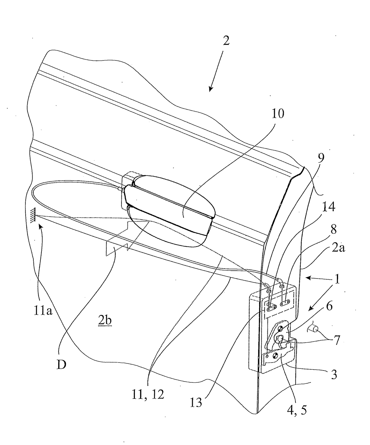
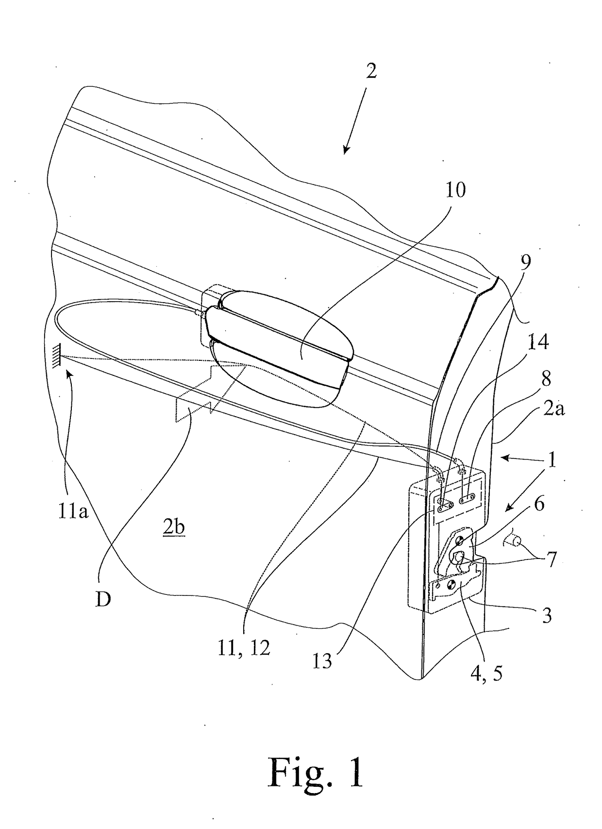
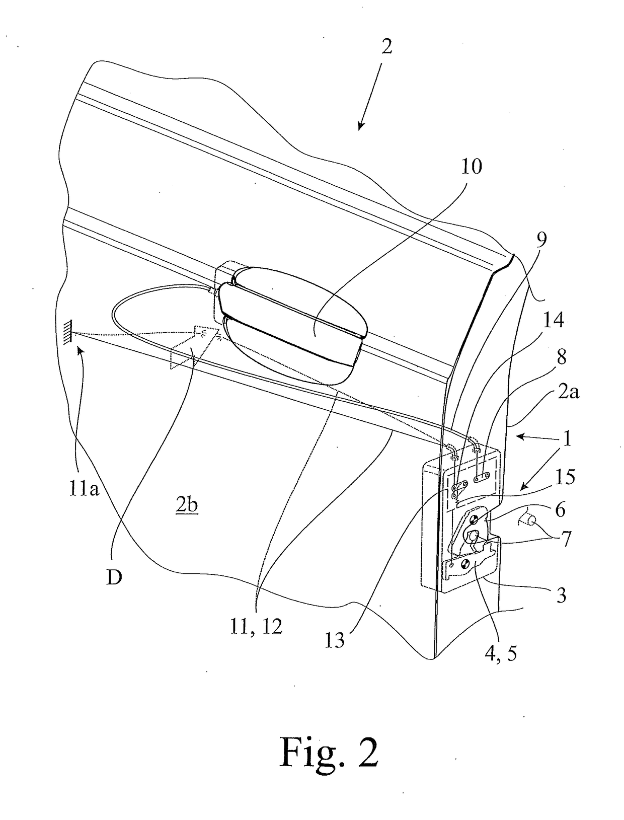
[0037]The proposed motor vehicle lock arrangement 1 is assigned to a motor vehicle door 2 as may be seen in FIG. 1. This motor vehicle lock arrangement 1 comprises a motor vehicle lock 3, which comprises a lock element 4. The deflection of the lock element 4 leads to opening the motor vehicle lock 3 and thereby the opening of the motor vehicle door 2. Here the lock element 4 is a pawl 5, which is assigned to a catch 6, which catch 6 may be brought into holding engagement with a lock striker 7 as is generally known from the state of the art. For the realization of the lock element 4 different alternatives exists, which may work with or without a catch 6.

[0038]The motor vehicle lock 3 comprises at least one actuation lever 8, which actuation may deflect the lock element 4 depending on the lock state of the motor vehicle lock 3. The deflection of the lock element 4 leads to opening of the motor vehicle lock 3 as noted above. In FIG. 1, an elongate force transmission element 9, here a B...


PUM


Abstract

Disclosed is a vehicle lock arrangement for a vehicle door, comprising a vehicle lock with a lock element such as a pawl, at least one actuation lever to deflect the lock element and thereby to open the vehicle lock, at least one elongate force transmission element, which couples the at least one actuation lever to a respective door handle. At least one crash detection element in the form of an elongate force transmission element for the transmission of pulling forces is provided, which in the installed state extends through a part of the motor vehicle door and is coupled to a control mechanism, which control mechanism may be switched to a disabling state.

Description

CLAIM OF PRIORITY[0001]This application claims the benefit of U.S. Provisional Application No. 62 / 218,165, filed Sep. 14, 2015, the content of which is herein incorporated by reference in its entirety.FIELD OF THE TECHNOLOGY[0002]The application is directed to a motor vehicle lock arrangement as well as to a motor vehicle door.BACKGROUND[0003]The motor vehicle lock arrangement is assigned to a motor vehicle door, which normally comprises an inner door shell and an outer door shell. The expression “motor vehicle door” is to be understood in a broad sense. It includes in particular side doors, back doors, lift gates, trunk lids or engine hoods. Such a motor vehicle door may generally be designed as a sliding door as well.[0004]The known motor vehicle lock arrangement (US 2014 / 0284940 A1), which is to be considered closest state of the art, comprises a motor vehicle lock with a lock element in the form of a pawl, which is assigned a catch. The catch is interacting with a lock striker i...

Claims


Application Information

Patent Timeline
IPC IPC(8): E05B77/04E05B79/10E05B85/24
CPCE05B77/04E05B79/10E05B85/243E05B79/20E05B79/22
Inventor ROSALES, DAVIDHANKE, STEPANWESTHOFF, NATHALIE
Owner BROSE SCHLIESSSYSTEME GMBH & CO KG
Learn More