
Apparatus and method for eliminating impulse interference

Inactive Publication Date: 2017-03-02
XUESHAN TECH INC
View PDF37 Cites 0 Cited by
  • Summary
  • Abstract
  • Description
  • Claims
  • Application Information

AI Technical Summary

Benefits of technology

The present invention is about a device and method to get rid of impulse interference. It works by adjusting a circuit that detects impulse interference, so it can effectively reduce the likelihood of being triggered by nearby interference. This invention can be used for DVB-C receiving systems and other systems that need to get rid of impulse interference.

Problems solved by technology

For a DVB-C system, external interference frequently occurring in the signal transmission process includes impulse interference, adjacent channel interface and co-channel interference.
However, apart from impulse interference, adjacent channel interference and co-channel interference may simultaneously occur in the input signal Sin.
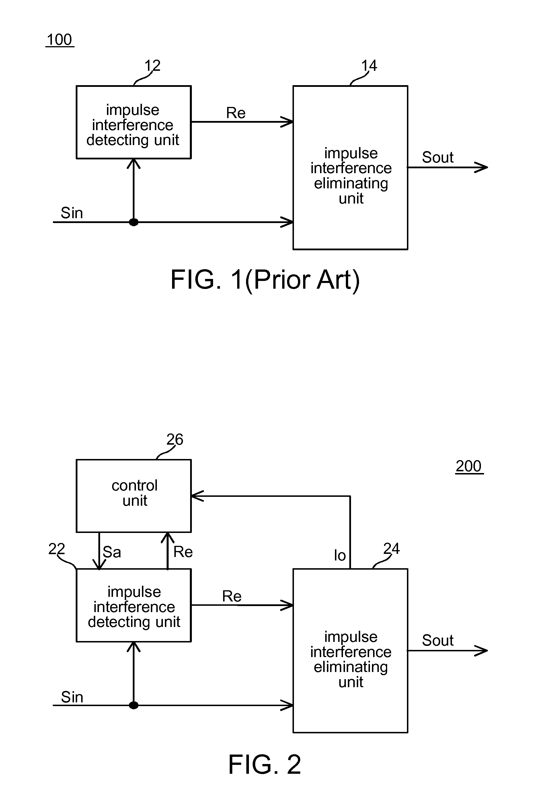
An input signal mixed with multiple types of interference may cause misjudgment of the impulse interference detecting circuit 12.
Erroneously triggering the impulse interference eliminating circuit 14 may cause undesirable effects on other performances on a system corresponding to the impulse interference eliminating apparatus 100.
However, the Reed-Solomon has a limited error correction capability.
If the number of erroneous symbols with unknown positions exceeds the number of symbols the Reed-Solomon decoder can correct, the packet may not be successfully decoded and become an erroneous packet.
It is known that, if the impulse interference detecting circuit 12 misjudges non-impulse interference as impulse interference, and the non-impulse interference does not in fact cause an error in the symbol at the position of the interference, the misjudged non-impulse interference may consume the error correction capability the Reed-Solomon decoder could have used for correcting erroneous symbols with unknown positions, hence resulting in an increased packet error rate in the output signal.

Method used


Image

  • Apparatus and method for eliminating impulse interference
  • Apparatus and method for eliminating impulse interference
  • Apparatus and method for eliminating impulse interference

Examples


Embodiment Construction

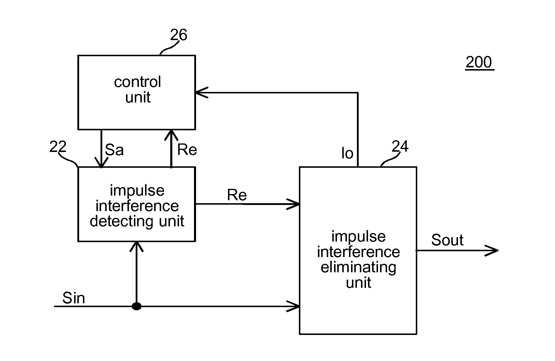
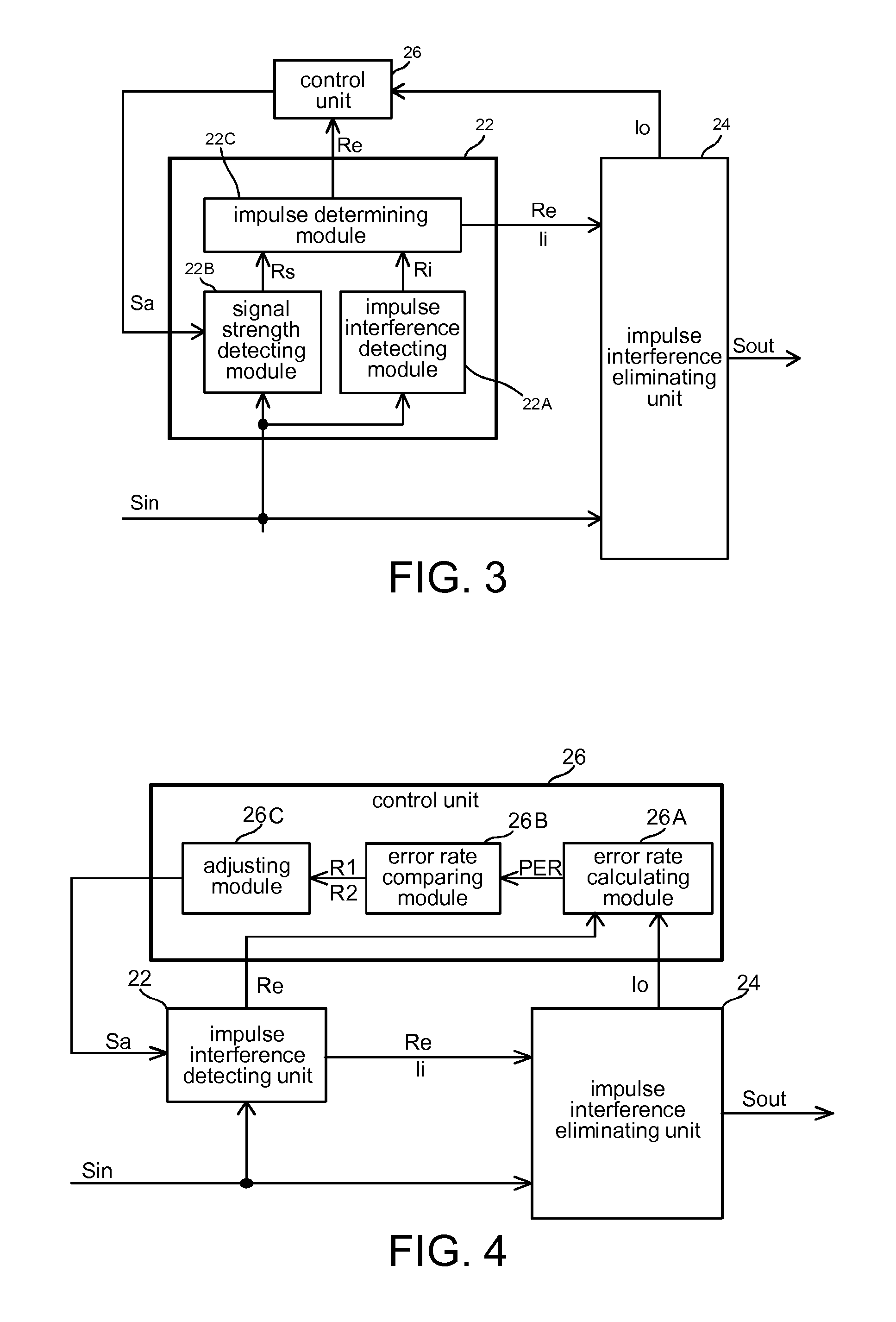
[0020]FIG. 2 shows a schematic diagram of an impulse interference eliminating apparatus 200 according to an embodiment of the present invention. The an impulse interference eliminating apparatus 200 includes an impulse interference detecting unit 22, an impulse interference eliminating unit 24 and a control unit 26.

[0021]In one embodiment, the impulse interference eliminating apparatus 200 may be disposed in a signal receiver end. The impulse interference detecting unit 22 detects whether impulse interference exists in an input signal Sin the signal receiver end receives according to a predetermined condition, and generates an impulse interference eliminating request Re when having detected that the input signal Sin satisfies the predetermined condition. In one embodiment, the predetermined condition includes whether an impulse characteristic appears in a waveform of the input signal Sin and whether signal strength of the input signal Sin is higher than a strength threshold. For exa...


PUM


Abstract

An apparatus for eliminating impulse interference includes an impulse interference detecting unit, an impulse interference eliminating unit and a control unit. The impulse interference detecting unit detects whether impulse interference exists in an input signal according to a predetermined condition, and generates an impulse interference eliminating request when having detected that the input signal satisfies the predetermined condition. In response to the impulse interference eliminating request, the impulse interference eliminating unit performs an impulse interference eliminating process on the input signal to generate an output signal. According to an output signal quality index associated with the output signal, the control unit selectively adjusts the predetermined condition used for detecting whether the impulse interference exists.

Description

[0001]This application claims the benefit of Taiwan application Serial No. 104128626, filed Aug. 31, 2015, the subject matter of which is incorporated herein by reference.BACKGROUND OF THE INVENTION[0002]Field of the Invention[0003]The invention relates to technologies for eliminating impulse interference.[0004]Description of the Related Art[0005]With the progress in communication technologies, the development of digital television broadcasting has also gradually matured. In addition to base stations and artificial satellites, digital television signals may also be transmitted through cable wires. The Digital Video Broadcasting-Cable (DVB-C) is one current common standard. For a DVB-C system, external interference frequently occurring in the signal transmission process includes impulse interference, adjacent channel interface and co-channel interference. In order to correct retrieve an input signal, a DVB-C receiver end needs to eliminate the effect that the above types of interfere...

Claims


Application Information

Patent Timeline
IPC IPC(8): H04B15/00H04L1/00H04L12/26
CPCH04B15/00H04L1/0076H04L43/0823H04L1/0047H04L1/0057H04L1/20H04B1/1036
Inventor JENG, YOU-TSAIYANG, FANG-MINGLEE, KUO-YULEI, KENG-LONTUNG, TAI-LAI
Owner XUESHAN TECH INC
Learn More