
Semiconductor laser device

a laser device and semiconductor technology, applied in semiconductor lasers, lighting and heating apparatus, transportation and packaging, etc., can solve problems such as the possibility of shifting of support members, and achieve the effect of less position shifting or misalignmen

Active Publication Date: 2017-03-02
NICHIA CORP
View PDF1 Cites 18 Cited by
  • Summary
  • Abstract
  • Description
  • Claims
  • Application Information

AI Technical Summary

Benefits of technology

The present invention aims to reduce the position shift of a support member in a semiconductor laser device caused by the thermal expansion of components. This invention ensures less misalignment of the support member, allowing the laser to direct light more reliably to a wavelength converting member.

Problems solved by technology

With a conventional semiconductor laser device, however, there is a possibility that a support member may be shift due to a difference in coefficient of thermal expansion inherent to materials of components.

Method used


Image

  • Semiconductor laser device
  • Semiconductor laser device
  • Semiconductor laser device

Examples


embodiment 1

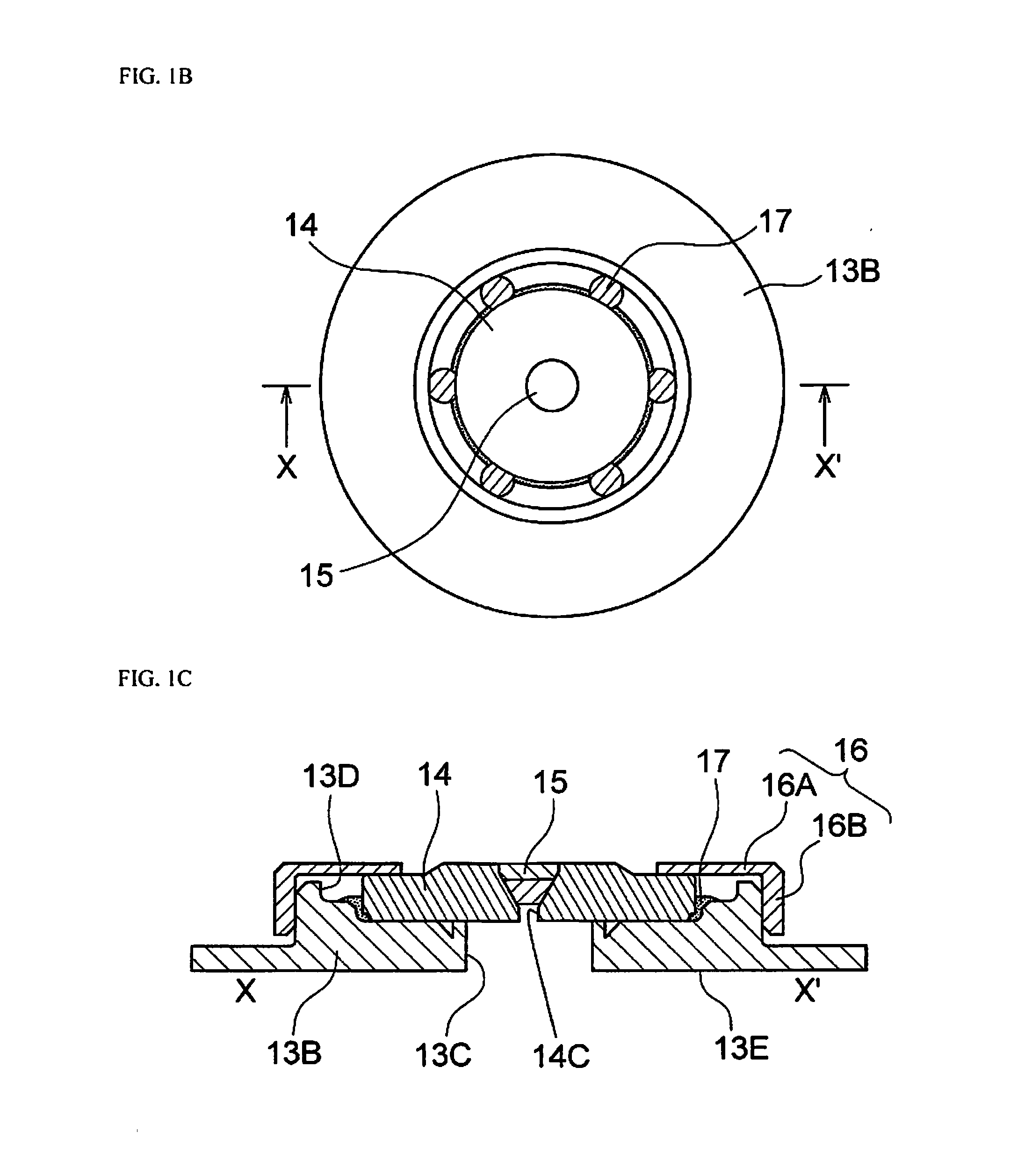
[0018]As shown in FIGS. 1A to 1D, the semiconductor laser device 10 in this embodiment has: a base 11; a semiconductor laser element 12 provided above the base 11; a lid 13 that is provided over the base 11, houses the semiconductor laser element 12, has a recess 13D formed in an upper portion of the lid 13 and having a lateral surface and a bottom, and has a through-hole 13C formed in the bottom of a recess 13D; a support member 14 that is disposed in the recess 13D, has a through-hole 14C that is smaller in diameter than the through-hole 13C of the lid 13 and above the through-hole 13C of the lid 13, has a coefficient of thermal expansion that is different from that of the lid 13, and has a lateral surface spaced from the lateral surface of the recess 13D; a wavelength converting member 15 that is supported in the through-hole 14C of the support member 14; a holding member 16 that is fixed to the lid 13 and holds an upper surface of the support member 14, and a buffer material 17 ...

embodiment 2

[0078]As shown in FIGS. 3A and 3B, in this embodiment, the configuration is substantially the same as that of the semiconductor laser device in Embodiment 1, except that the lateral surface of a recess 33D of a second lid 33B is not stepped.

[0079]Again in this embodiment, position shift of the support member 14 in the lateral direction and the like can be prevented.

[0080]The semiconductor laser device in the embodiments of the present invention can be used for in- or on-vehicle applications such as a headlight, a light source of backlight; a variety of lighting; a variety of display devices such as display, billboard, or destination screen; or a variety of light sources for various kinds of a projector.


PUM


Abstract

A semiconductor laser device includes a base, a semiconductor laser element, a lid, a support member, a wavelength converting member, a holding member, and a buffer material. The lid has a recess formed in an upper portion of the lid, and a through-hole formed in the bottom of the recess. The support member is disposed in the recess and has a through-hole. A diameter of the through-hole of the support member is smaller than that of the through-hole of the lid. A coefficient of thermal expansion of the support member is different from that of the lid. The wavelength converting member is supported in the through-hole of the support member. The holding member is fixed to the lid and holds the support member. The buffer material is disposed in at least a part of a space to between the lateral surfaces of the recess and the support member.

Description

CROSS-REFERENCE TO RELATED APPLICATIONS[0001]This application claims priority to Japanese Patent Application No. 2015-169117 filed on Aug. 28, 2015. The entire disclosure of Japanese Patent Application No. 2015-169117 is hereby incorporated herein by reference.BACKGROUND[0002]1. Technical Field[0003]The present disclosure relates to a semiconductor laser device.[0004]2. Description of Related Art[0005]A semiconductor laser device that combines a semiconductor laser element with a wavelength converting member, which is disposed above the semiconductor laser element, has been proposed in the past (for example, JP2008-147289A). With this device, the wavelength converting member is fixed in a state of being pressed against a package by a holding member so that the wavelength converting member will not fall out.SUMMARY[0006]With a conventional semiconductor laser device, however, there is a possibility that a support member may be shift due to a difference in coefficient of thermal expan...

Claims


Application Information

Patent Timeline
Patent Type & Authority Applications(United States)
IPC IPC(8): H01S5/022H01S5/30
CPCH01S5/02208H01S5/02272H01S5/02296H01S5/02288H01S5/3013F21S41/16F21S41/176F21S41/192F21S43/195H01S5/02212H01S5/02469H01S5/0087H01S5/02257H01S5/02253H01S5/0237
Inventor MORIZUMI, NAOTONAMIE, TAKASHINAKAGAWA, TAKASHIKOMODA, DAISUKESHOZUI, HIROAKI
Owner NICHIA CORP
Learn More