Bookmaking apparatus

A paper stack and component technology, which is applied in book binding, adhesive for binding, transportation and packaging, etc., can solve the problems of increasing the overall size of the device, complex device support structure, and high power.

Active Publication Date: 2010-02-24
NISCA KK
View PDF4 Cites 4 Cited by
  • Summary
  • Abstract
  • Description
  • Claims
  • Application Information

AI Technical Summary

Problems solved by technology

[0017] For example, in this guide mechanism, like a binding device, in the case where the tray position of the basic horizontal posture is transferred to the sizing position of the basic vertical posture, the trajectory of the transfer is complicated.
[0018] This guide mechanism is not disclosed in the above-listed Patent Document 1, but it includes a guide, which is complicated in order to deflect the paper bundle from a horizontal posture to a vertical posture for conveyance; The structure is also complex
[0019] As in Patent Document 1, in the case of rotating the paper bundle pulled out from the tray in a substantially horizontal direction to deflect its posture, an area for rotation must be required between the paper discharge path and the tray, resulting in an increase in the overall size of the device.
[0020] As mentioned above, when the paper bundle is conveyed by the gripping mechanism in a vertical posture, the gripping force is determined by the size of the gripping member and the gripping pressure, and there is a problem that the stack posture is tilted or the paper falls during transportation. To prevent this problem, the area of ​​the clamping parts must be increased, and the clamping pressure must be increased. However, when the paper bundle is from a small size type such as JI SB6 size to a large size paper such as JISA3 size, clamping The holding area is limited, and in order to increase the holding pressure, there are problems that the size of the drive source such as the motor, actuator, etc. is increased and the power is high.

Method used


Image

  • Bookmaking apparatus
  • Bookmaking apparatus
  • Bookmaking apparatus

Examples


Embodiment Construction

[0102] The present invention will be specifically described below based on the binding device of the present invention shown in the drawings.

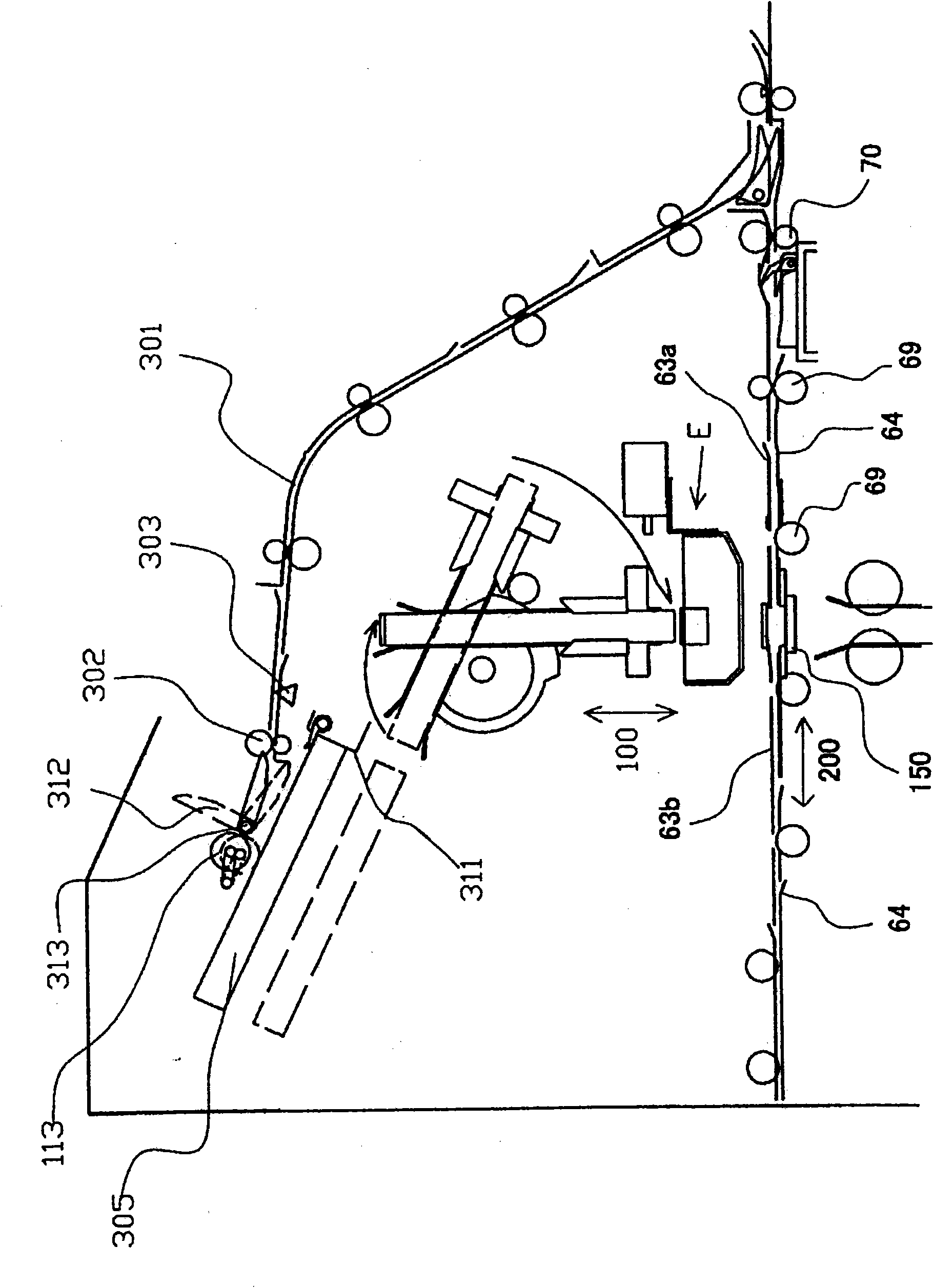
[0103] Figure 1A It is an explanatory diagram of the overall structure of the bookbinding system adopting the present invention, Figure 1B An explanatory diagram of its main parts.

[0104] figure 2 is an overall explanatory diagram of the stacked disc assembly, Figure 6 This is an overall explanatory diagram of the stack transport mechanism.

[0105] Figure 19A and 19B is an explanatory diagram of the main parts of the cover transport mechanism, Figure 26A and 26B It is an explanatory diagram of the operation of the paste application unit.

[0106] Figure 1A and 1B The bookbinding system shown is composed of the following parts including an image printing unit A which sequentially prints sheets; Middle; stacking tray assembly C, the stacking tray assembly C loads paper from the image printing assembly A in page order; ...


PUM


Abstract

The objective of the invention is that, sheets are loaded in a stacked state to every trays, the neat and aligned tray members are moved from a loading position to a lower position leaving downward ina predetermined amount, and then rotating area of subsequent sheet bundles is assured, and at the same time, a regular processing is proceeded in a situation without any sheet bundles falling down, and then the device can be composed smally and compactly. The device according to the invention comprises a discharge path operable to sequentially convey the sheet from a discharge outlet; a tray arranged substantially horizontally below a discharge outlet of an image forming apparatus; a gripping conveyance device configured to convey a sheet bundle received from the tray to a finishing device ata substantially vertical posture and turned a predetermined angle; a post-processing means arranged below the gripping conveyance device for processing the sheet bundle turned by the gripping conveyance device, and the tray means is configured to rise and lower for a predetermined distance between a sheet stacking position and a sheet bundle conveyance position below the sheet stacking position.

Description

[0001] The present invention is a divisional application of the No. 200610087290.3 invention patent application filed on June 14, 2006 with the title of "paper bundle conveying device and binding device". technical field [0002] The present invention relates to a post-processing device for image forming devices such as printers, printing machines, and copiers. The present invention relates to loading paper printed by an image forming device on a tray, aligning them in a stack in page order, and binding the stack of paper Together, the bundle conveying device in the bookbinding system and the binding device using it. Background technique [0003] In general, such a device is widely used as a terminal device of an image forming device such as a printer or a printing machine, and is widely used to stack paper on which images have been formed on a page-by-page basis, align them in a booklet, sizing the end faces, and binding them on the cover. Binding system on paper. [0004]...

Claims


Application Information

Patent Timeline
Patent Type & Authority Applications(China)
IPC IPC(8): B42C19/00B42C19/08B42C9/00B42C11/00B65H37/04
Inventor 永泽惠一津久井明彦高木胜雅中迂浩
Owner NISCA KK
Why Eureka
Try Eureka