
Magnetic switch assembly and stylus having the same

a technology of magnetic switch and assembly, which is applied in the direction of magnetic/electric field switch, instruments, computing, etc., can solve the problems of limiting users' capabilities, reducing convenience, and reducing user's ability

Inactive Publication Date: 2017-03-02
ADONIT
View PDF6 Cites 4 Cited by
  • Summary
  • Abstract
  • Description
  • Claims
  • Application Information

AI Technical Summary

Benefits of technology

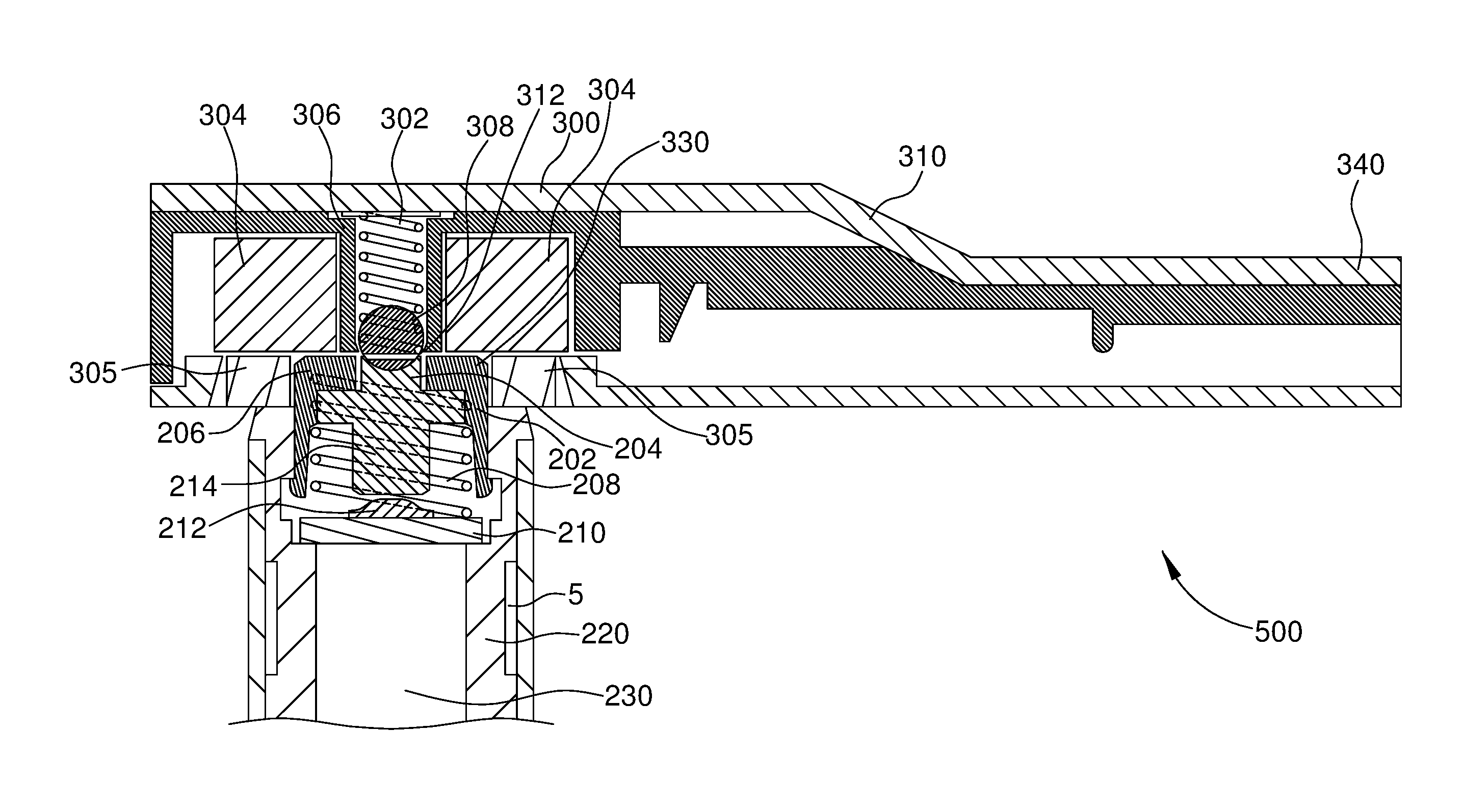
The invention provides a magnetic switch assembly for a charging apparatus and a switching apparatus that work together to enable charging of a stylus. The assembly includes a housing, a spring, a magnet, an insulator layer, and a ball member. When the charging apparatus is connected to the stylus, power is supplied through a metal plate to the stylus' power source. Additionally, the invention includes a chamfered insulator layer to restrict movement of the ball member, and a turn-on and turn-off function for the stylus. Overall, the invention enables efficient charging and operation of the stylus using a magnetic switch assembly.

Problems solved by technology

This eliminates the user's ability to use a fingertip to interact with the touchscreen, drastically reducing convenience and requiring that special hardware (the stylus) be developed and kept with the device.
Touchpad capacitive sensors are designed to require close proximity to avoid accidental touch detection, further limiting their capabilities.
But this does not work for standard capacitive touchscreens which are designed to detect the capacitance of a user's fingertip; instead, special hardware for these touchscreens requires the use of a special stylus, thereby entirely preventing users from using their fingertips.
However, styluses usually have clumsy solutions for switching the device on or off and charging their internal batteries.

Method used


Image

  • Magnetic switch assembly and stylus having the same
  • Magnetic switch assembly and stylus having the same
  • Magnetic switch assembly and stylus having the same

Examples


Embodiment Construction

[0027]The following detailed description of embodiments references the accompanying drawings that form a part hereof, in which are shown various illustrative embodiments through which the invention may be practiced. In the drawings, like reference numbers indicate like features or functionally identical steps. The embodiments are described in sufficient detail to enable those skilled in the art to practice the invention, and it is to be understood that other embodiments may be utilized and that logical changes may be made without departing from the spirit and scope of the invention. The detailed description is therefore not to be taken in a limiting sense, and the scope of the invention is defined solely by the appended claims.

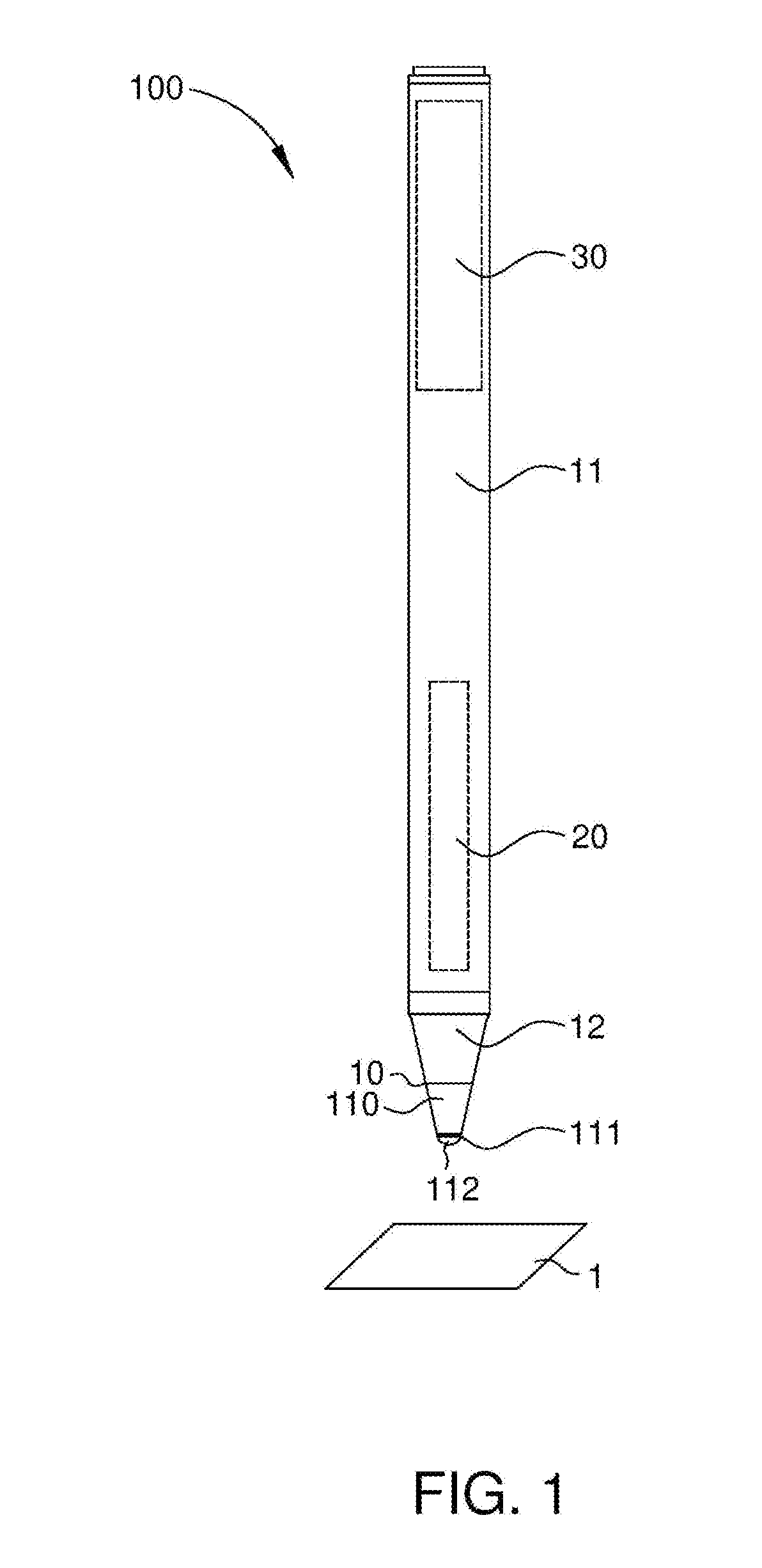
[0028]Please refer to FIG. 1, which is a perspective view of a stylus 100 and a touchscreen 1 according to an embodiment of the invention. In the present embodiment, the stylus 100 includes a tip 10, a body 11, a fairing 12, an emitting electrode 110, a sensin...


PUM


Abstract

Embodiments of a magnetic switch assembly and a stylus having the magnetic switch assembly are disclosed. The magnetic switch assembly includes a charging apparatus and a switching apparatus. The charging apparatus includes a housing, a first spring, a first magnet, a second magnet, an insulator layer, and a ball member. The first magnet, the second magnet, and the insulator layer form a recess region with the ball member situated in the center of the recess region. The switching apparatus includes a button, a second spring, and a metal plate. The button includes a contact part and an insulating part. The metal plate has a contact pad disposed on the metal plate. When the button is situated in the recess region of the charging apparatus, power is supplied from the charging apparatus to a power source electrically connected to the metal plate.

Description

CROSS REFERENCE TO RELATED APPLICATIONS[0001]This application claims the benefit of priority to U.S. provisional patent application No. 62 / 209,347, filed Aug. 25, 2015, entitled “MAGNETIC SWITCH ASSEMBLY AND STYLUS HAVING SAME”, which is hereby incorporated by reference in its entirety for all purposes.BACKGROUND[0002]Field of the Invention[0003]The disclosure relates to a magnetic switch assembly and a stylus having the same, and more particularly to a stylus capable of being switched and charged through the magnetic switch assembly.[0004]Description of Related Art[0005]Generally speaking, styluses for use with capacitive touchscreens require a minimum level of capacitance between the stylus and the touchscreen for the capacitive sensor in the touchscreen to accurately detect the position of the stylus. Nowadays, most such styluses are passive, having a wide conductive tip that is electrically coupled to the stylus body, such that when the body is gripped by a user, the user is ele...

Claims


Application Information

Patent Timeline
Patent Type & Authority Applications(United States)
IPC IPC(8): G06F3/0354H01H36/00
CPCH01H36/008G06F3/03545G06F2200/1632
Inventor ZELIFF, ZACHARY JOSEPHBLOEM, REINIERKAO, TING-KUO
Owner ADONIT
Learn More