
Vehicle front structure

a front structure and vehicle technology, applied in the field of vehicle front structure, can solve the problems of preventing the absorption of frontal impact load through the deformation of front side frames, and the front structures are not capable of absorbing frontal impact load, so as to facilitate the downward bending of the reinforcing member and improve the rigidity

Active Publication Date: 2017-03-02
HONDA MOTOR CO LTD
View PDF2 Cites 9 Cited by
  • Summary
  • Abstract
  • Description
  • Claims
  • Application Information

AI Technical Summary

Benefits of technology

The patent text describes a vehicle suspension system that improves the rigidity and impact absorption of various members that support the power steering unit and other steering system components. The system includes a cross member and front side frames reinforced by right and left braces, as well as a rear side support portion and front side frames that are supported by a dash cross member. This arrangement allows for more efficient absorption of impact loads and reduces bending moments, providing better protection for the vehicle occupants. Additionally, the system includes an elastic portion in the rear side support portion that allows for tilt-adjustment and separation from the mount during a frontal impact, improving the overall performance of the suspension system.

Problems solved by technology

Such vehicle front structures are not capable of absorbing a frontal impact load through subframes.
This arrangement may impede the absorption of a frontal impact load through the deformation of front side frames.

Method used


Image

  • Vehicle front structure
  • Vehicle front structure
  • Vehicle front structure

Examples


embodiment

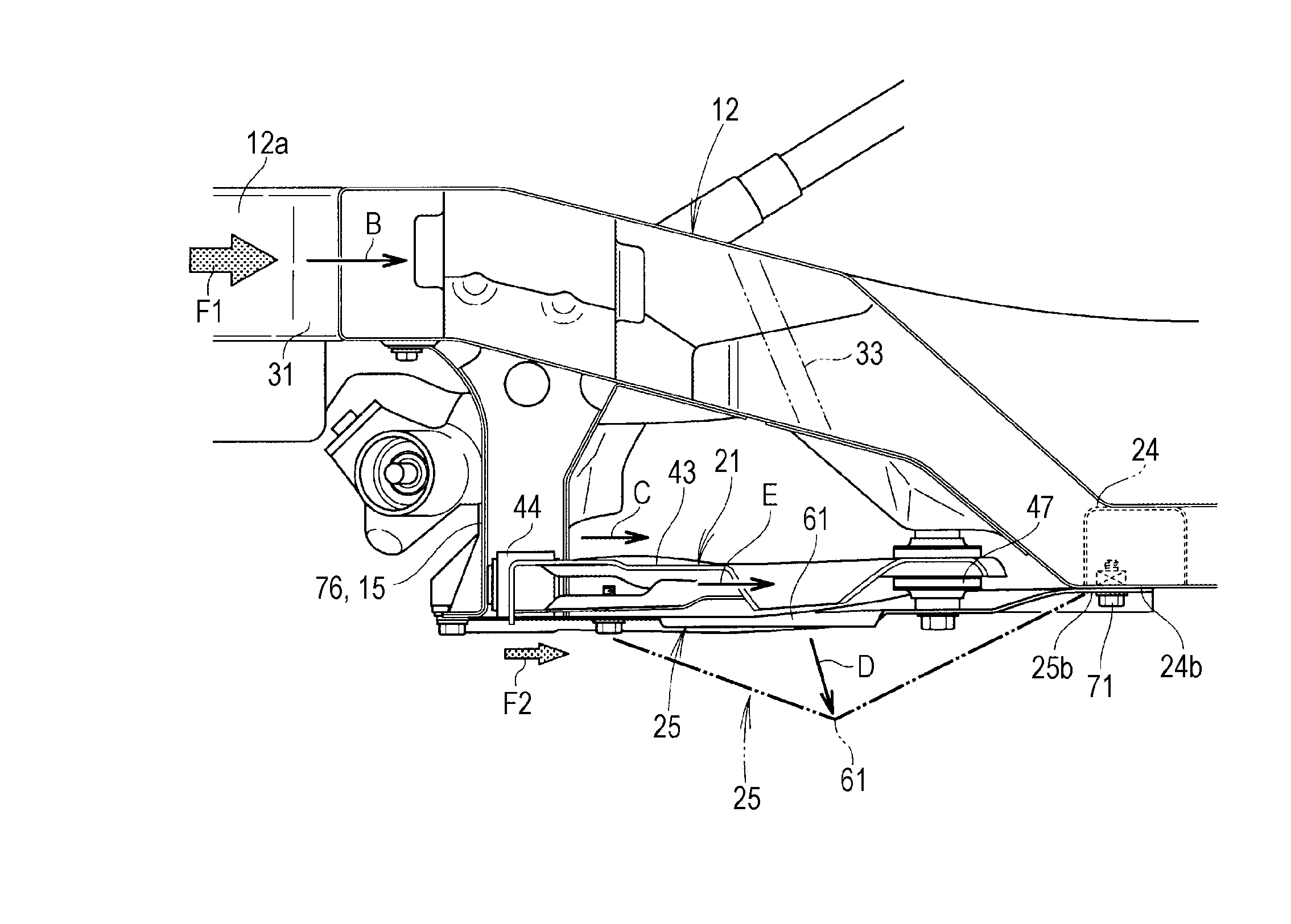
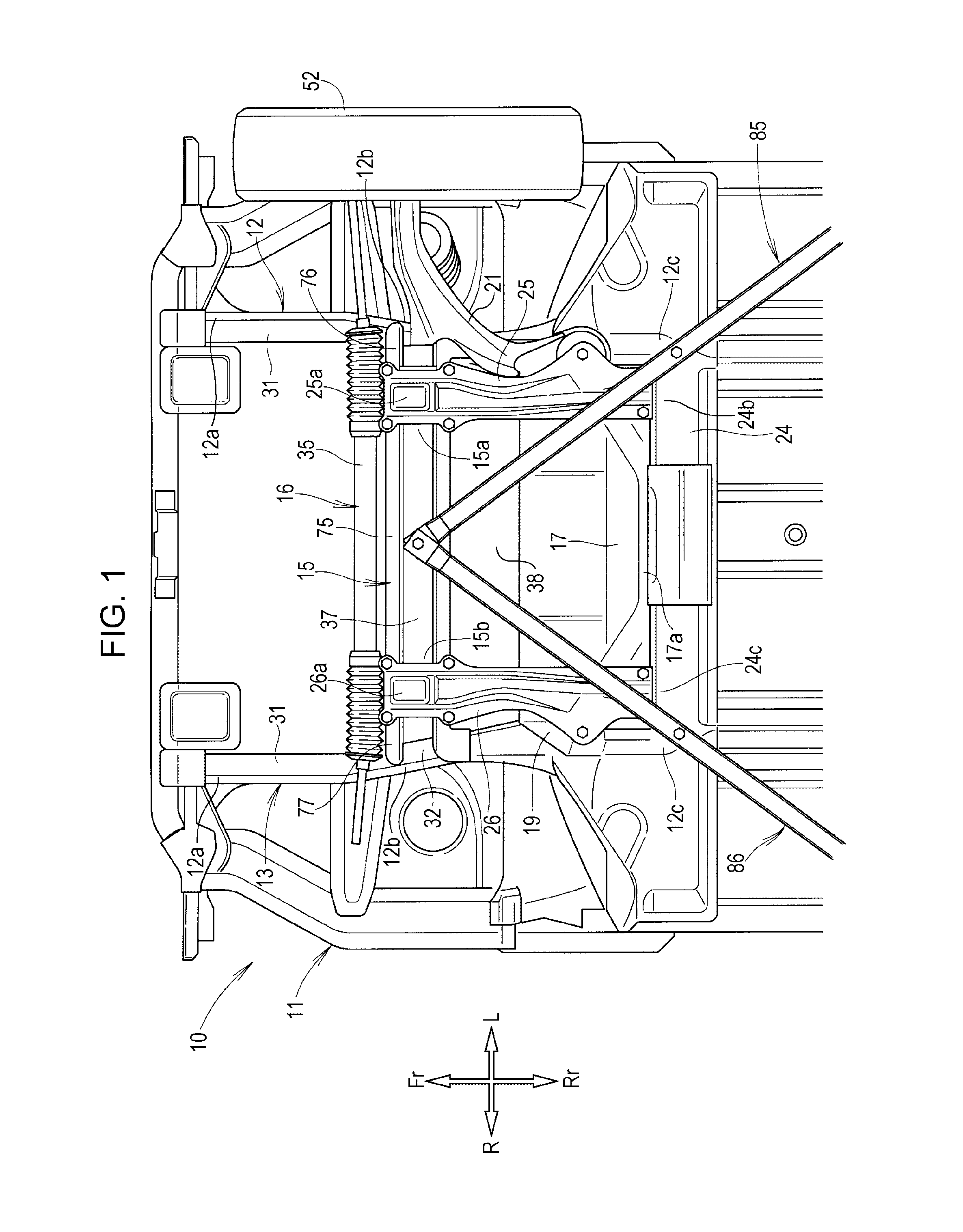
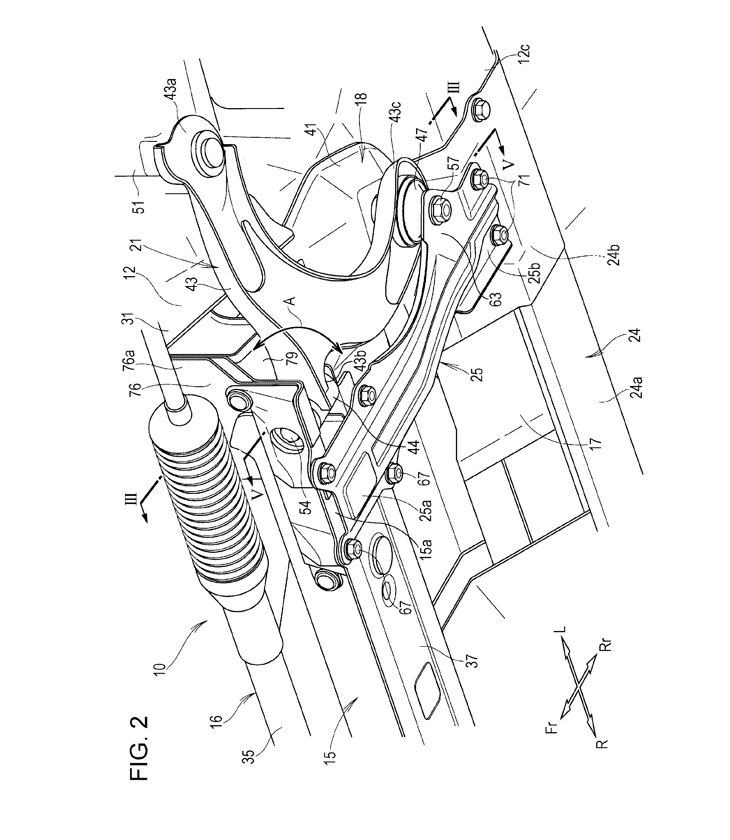
[0027]A vehicle front structure 10 according to an embodiment is described below. As illustrated in FIGS. 1 and 2, the vehicle front structure 10 has right and left front side frames 12 and 13 provided respectively on the right and left sides of a vehicle body 11, a cross member 15 installed across the right and left front side frames 12 and 13, and a power steering unit 16 provided along the cross member 15.

[0028]In addition, the vehicle front structure 10 has a dash panel 17 behind the cross member 15, a left mount 18 provided on the left front side frame 12 on the side of the dash panel 17, and a right mount 19 provided on the right front side frame 13 on the side of the dash panel 17.

[0029]Furthermore, the vehicle front structure 10 has a left suspension arm 21 supported by the cross member 15 and the left mount 18, a right suspension arm (not illustrated) supported by the cross member 15 and the right mount 19, a dash cross member 24 installed across the left front side frame 1...


PUM


Abstract

A vehicle front structure includes a cross member installed across right and left front side frames. The left front side frame has a frame bending section provided above a left suspension arm. The frame bending section is formed so as to be bendable when subjected to a frontal impact load. A left reinforcing member is disposed below the frame bending section and is mounted across the cross member and the dash cross member. The left reinforcing member is fastened to a rear fastening portion. The left reinforcing member has a bending section that is bendable downward when subjected to an impact load.

Description

CROSS REFERENCES TO RELATED APPLICATIONS[0001]The present application claims priority under 35 U.S.C. §119 to Japanese Patent Application No. 2014-174197, filed Aug. 28, 2014, entitled “VEHICLE FRONT STRUCTURE”. The contents of this application are incorporated herein by reference in their entirety.BACKGROUND[0002]1. Field[0003]The present disclosure relates to a vehicle front structure that has front side frames provided on right and left sides thereof and suspension arms supported below the front side frames.[0004]2. Description of the Related Art[0005]Some vehicle front structures have subframes provided below right and left front side frames and have engines or other power sources supported by the subframes. A subframe is a highly rigid member that supports an engine or other power source. When subjected to a frontal impact load, such a highly rigid subframe bends, thereby absorbing the impact load (see, for example, Japanese Unexamined Patent Application Publication No. 2005-27...

Claims


Application Information

Patent Timeline
IPC IPC(8): B62D21/15B62D21/11
CPCB62D21/11B62D21/152
Inventor TAGUCHI, YUKI
Owner HONDA MOTOR CO LTD
Learn More