
Manufacturing method and structure of carbon fiber rims

Active Publication Date: 2017-03-02
ALEX GLOBAL TECH
View PDF4 Cites 0 Cited by
  • Summary
  • Abstract
  • Description
  • Claims
  • Application Information

AI Technical Summary

Benefits of technology

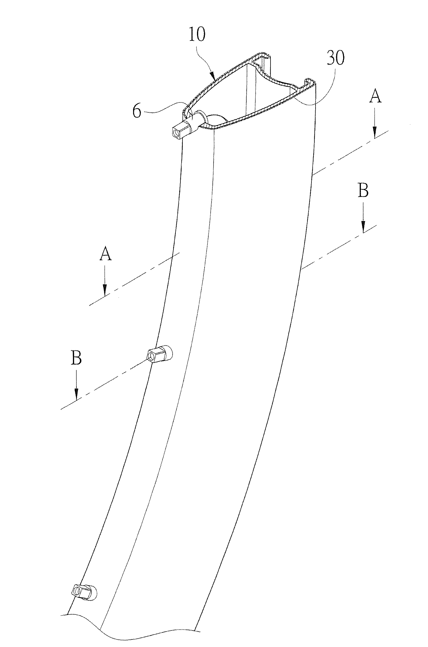
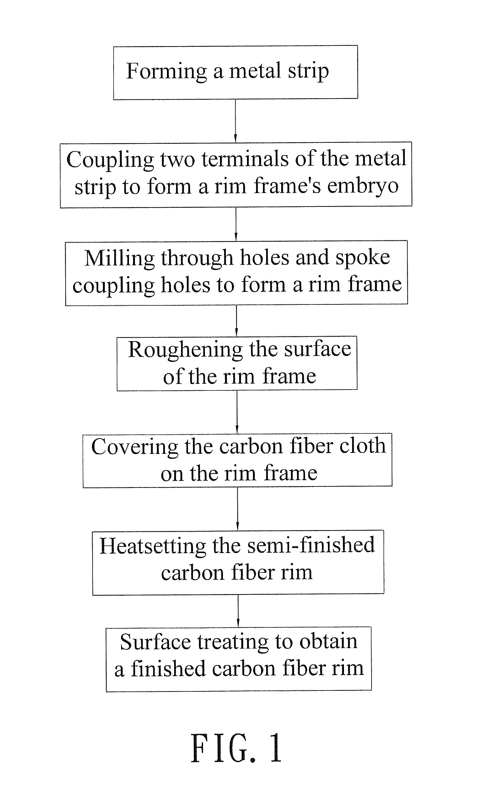
The invention is a method and structure for manufacturing a carbon fiber rim. The method involves forming a metal strip with a needed shape, connecting the metal strip to form a rim frame, and then covering the rim frame with a carbon fiber cloth. The carbon fiber cloth is trimmed to a suitable shape and covers the inner rim wall and through holes in the rim frame. The method also includes treating the surface of the semi-finished carbon fiber rim to form a finishing carbon fiber rim. The carbon fiber rim has advantages of light weight and good structure strength. The method reduces the number of laminating carbon fiber cloth layers, decreases working hours and processes, and increases the yield.

Problems solved by technology

However, since manufacturing the traditional carbon fiber wheels needs sequentially covering multi layers of carbon fiber cloth, the manufacturing construction is quite time-consuming and labor-consuming.
If air is remained, the layers of the carbon fiber cloth cannot be completely and smoothly laminated, and defective with local protruding is thus produced.
Therefore, the traditional manufacturing method cannot effectively decrease the defect rate of the carbon fiber wheels.
Moreover, the price of the carbon fiber cloth is expensive, and the cost of laminating multi layers of carbon fiber cloth is thus increased.
This method still has the disadvantages of the traditional manufacturing method of carbon fiber wheels.
That is, 5-7 layers of carbon fiber prepregs are needed, and thus the manufacturing is time-consuming, high cost, and the defect rate cannot be decreased, as well as it has to be noticed that whether bubbles are generated between adjacent layers when laminating.
Moreover, although the rim made of carbon fiber cloth has the excellent effect of light weight, the carbon fiber wheel cannot meet the requirement of the structure strength and thus deformed easily.

Method used


Image

  • Manufacturing method and structure of carbon fiber rims
  • Manufacturing method and structure of carbon fiber rims
  • Manufacturing method and structure of carbon fiber rims

Examples


embodiment

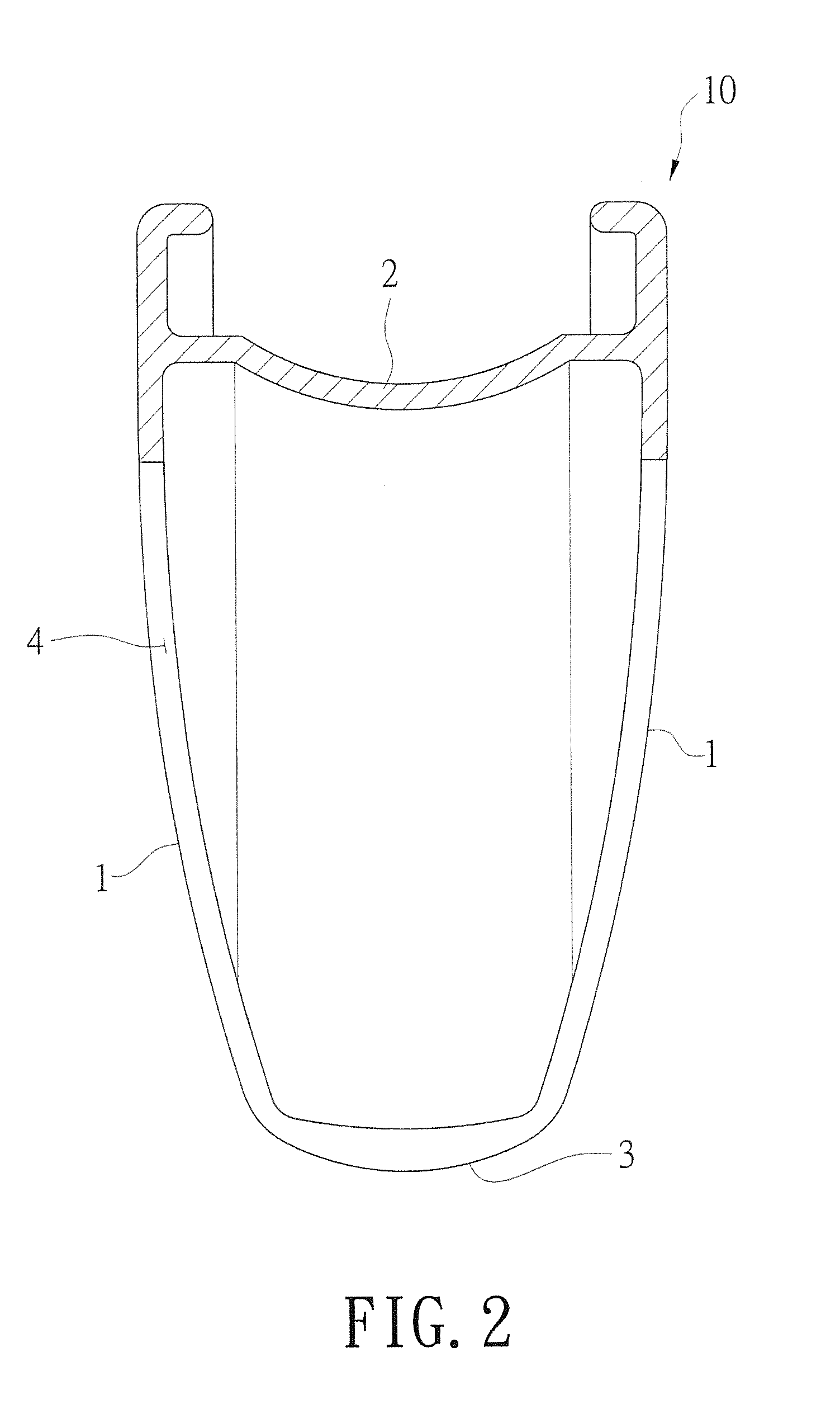
[0068]An aluminum alloy was heated to a moldable temperature and then extruded to form a metal strip having a width of 25 mm and a height of 29 mm. The metal strip comprises two side walls (1), a connecting wall (2) connecting opposite terminal surfaces of the side walls (1), an inner rim wall (3) connecting the radial inner edges of the side walls (1) to form a space surrounded by the side walls (1), the connecting wall (2), and the inner rim wall (3). The meaning of the “width' are the distance between the two side walls (1), and the meaning of the “height” is the distance from the bottom to the top of the side walls (1). Next, the two terminals of the strip are connected to form a circle as a rim frame's embryo. The rim frame's embryo is milled to form through holes (4) including the two side walls (1) and the inner rim wall (3) as well as the spoke coupling holes (5) on the inner rim walls (3). The spoke coupling holes (5) and the through holes (4) are disposed alternatively to ...


PUM

PropertyMeasurementUnit
Temperatureaaaaaaaaaa
Weightaaaaaaaaaa
Structureaaaaaaaaaa

Abstract

A manufacturing method and structure of a carbon fiber rim is revealed. A metal strip is formed by heating a metal substrate to a moldable temperature and then extruded molding. The metal strip comprises two side walls, a connecting wall and an inner rim wall to form a space surrounded by the side walls, the connecting wall, and the inner rim wall. Next, two terminals of the strip are connected to form a circle as a rim frame's embryo. The two side walls, or the two side walls and the inner rim wall of the rim frame's embryo are milled to form plural through holes and become a rim frame. Afterwards, the surface of the rim frame is roughened and covered with a trimmed carbon fiber cloth having a predetermined shape. After heatsetting and surface treating, a carbon fiber rim having a light weight and a strong structure is obtained.

Description

BACKGROUND OF THE INVENTION[0001]Field of Invention[0002]The disclosure relates to a manufacturing method and structure of a carbon fiber rim, especially relates to a rim frame's embryo having many through holes and covered by a carbon fiber cloth, whereby a rim having a light weight and a strong structure is obtained.[0003]Description of Related Art[0004]In addition to as a basic means of transportation, bicycles also has composite functions of recreation and sports. After the elevation of research and development ability and the progress of technology, the appearance, ride comfort, body strength, weight, and speed of bicycle all become development focus. Especially for professional athletics racing bike, ride comfort, body strength, weight, and speed are absolutely the goals of the riders.[0005]In order to develop the bicycle toward the direction of lightweight construction, wheels made of carbon fibers have replaced the traditional metal wheels to effectively reduce the total wei...

Claims


Application Information

Patent Timeline
IPC IPC(8): B60B1/00B60B21/06B60B21/02
CPCB60B1/006B60B21/02B60B21/062B60B1/003B60B2310/214B60B2310/232B60B2900/311B60B2310/242B60B2310/52B60B2360/10B60B2360/3416B60B2900/111B60B2310/60B60B5/02B60B2310/204B60B2310/321B60B2310/618B60B2310/80
Inventor CHEN, WEI-CHIN
Owner ALEX GLOBAL TECH
Learn More