
Systems and methods for providing ultrasound guidance to target structures within a body

a technology of ultrasound guidance and target structures, applied in the field of ultrasound probes, can solve the problems of difficult to reliably and continuously direct the instrument to the target structure without complications, and the current ultrasound probes are limited in the guidance they provid

Active Publication Date: 2017-03-02
BULJUBASIC NEDA
View PDF18 Cites 10 Cited by
  • Summary
  • Abstract
  • Description
  • Claims
  • Application Information

AI Technical Summary

Benefits of technology

The present invention is an ultrasonic probe that includes a housing, two ultrasonic transducer arrays, two light sources, and a control panel. The ultrasonic probe can be used to direct an instrument to a target structure beneath a surface. The first ultrasonic beam is emitted in a first direction within a first plane, and the second ultrasonic beam is emitted in a second direction within a second plane that is perpendicular to the first plane. The first light line is projected within the first plane, and the second light line is projected within a third plane that intersects the first and second planes at an angle. The first and second images can be displayed simultaneously, and the centerline of the second image is aligned with the centerline of the first image. The method also includes aligning the second planar ultrasonic beam over the target structure and selecting the desired angle of entry and point of entry on the first image. The technical effects of the invention include improved accuracy in directing the instrument to the target structure and improved image quality for guiding the instrument.

Problems solved by technology

Unfortunately, despite the improvements in ultrasound technology, as well as training and operator skills, it is still difficult to reliably and continuously direct the instrument to the target structure without complications.
While an improvement over unguided approaches, current ultrasound probes are still limited in the guidance that they provide.

Method used


Image

  • Systems and methods for providing ultrasound guidance to target structures within a body
  • Systems and methods for providing ultrasound guidance to target structures within a body
  • Systems and methods for providing ultrasound guidance to target structures within a body

Examples


Embodiment Construction

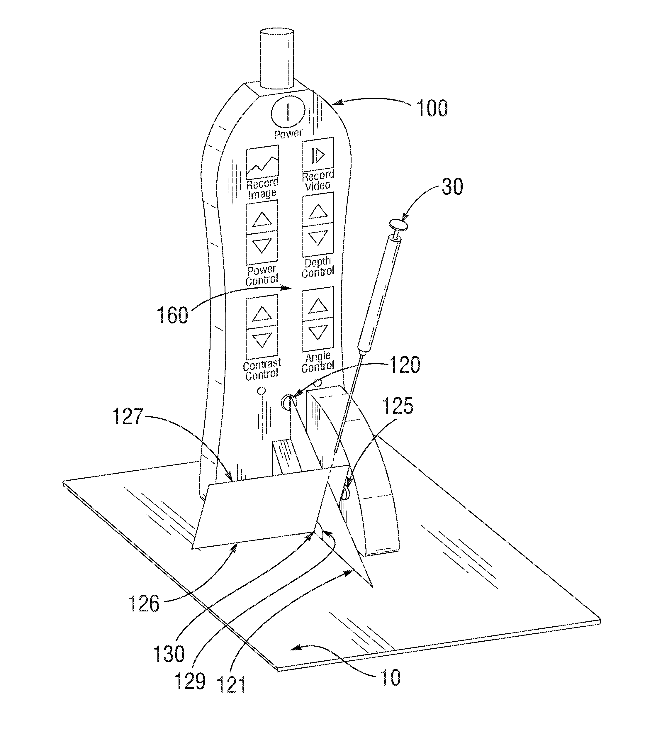
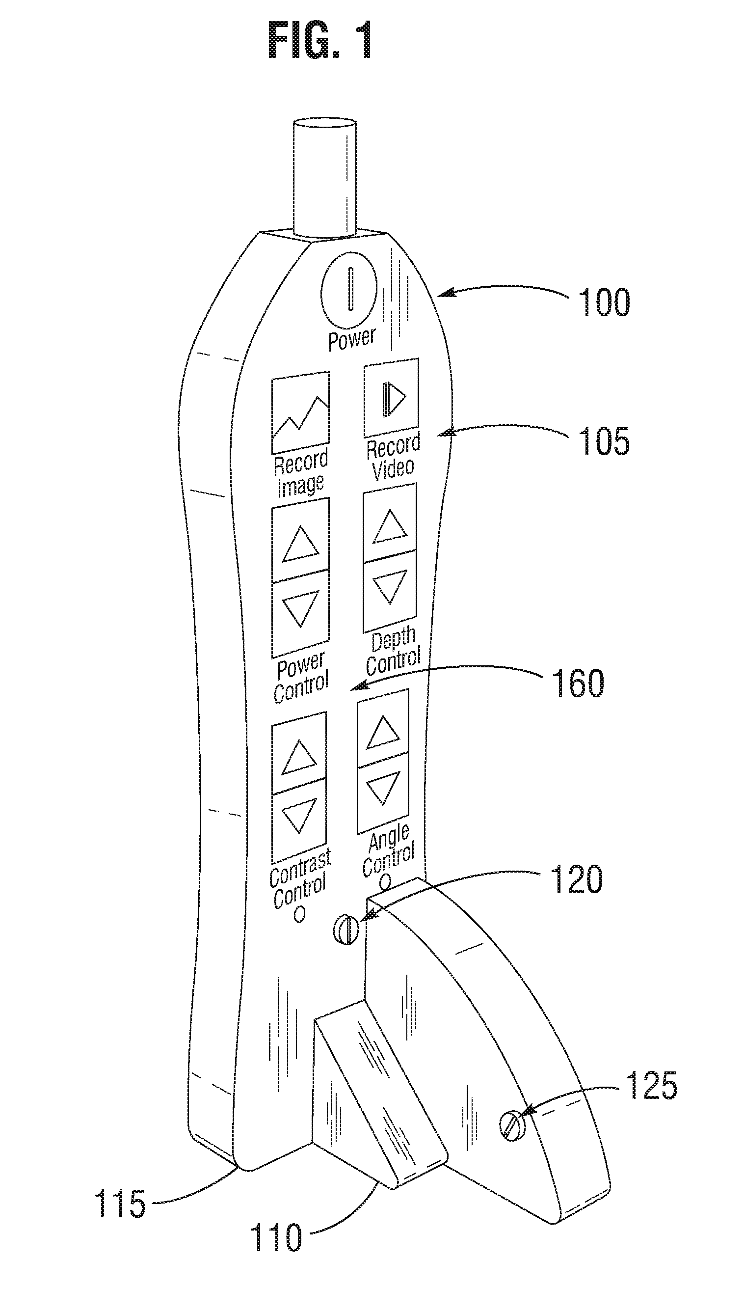
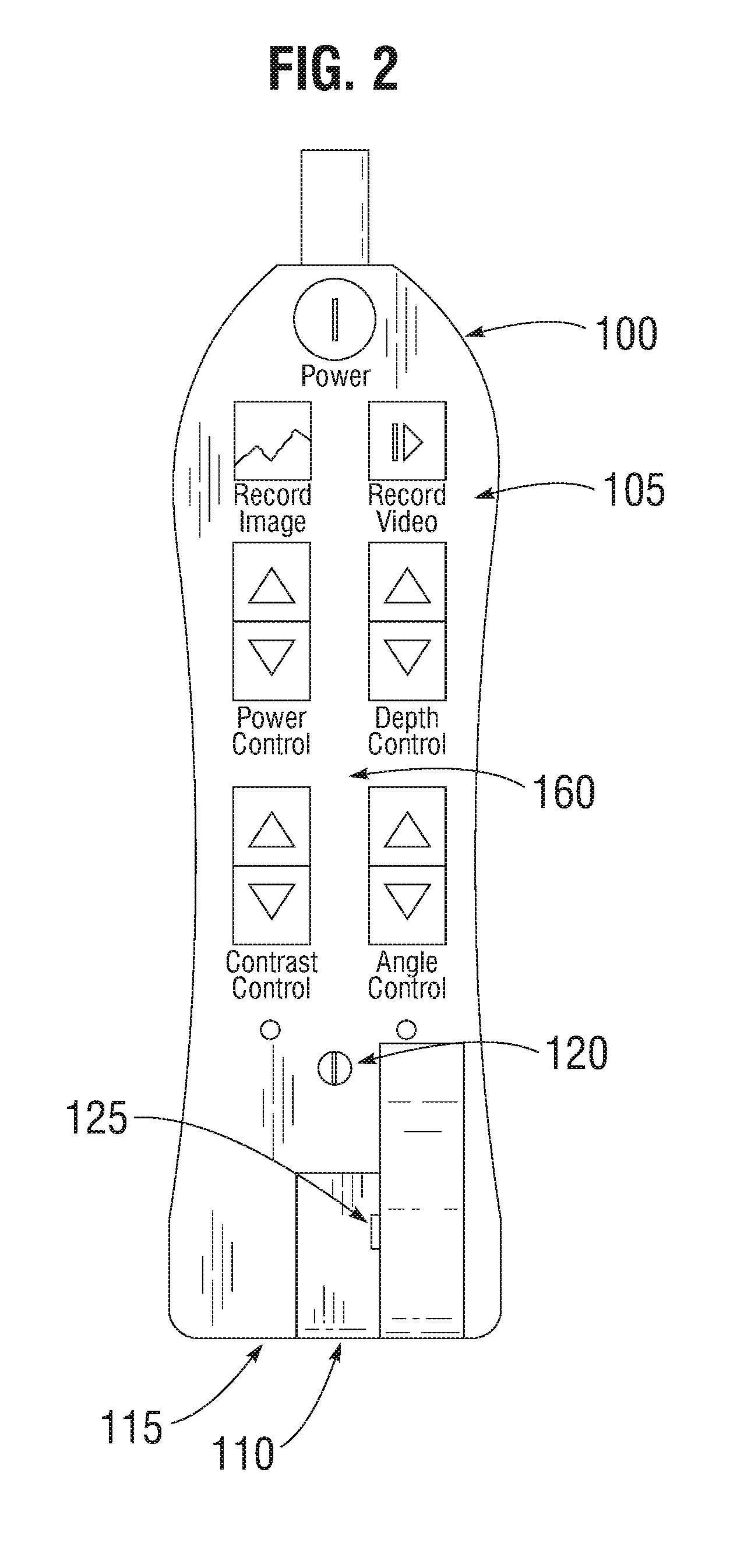
[0036]With reference now to FIGS. 1-6 of the illustrative drawings, there is shown an ultrasound probe 100 in accordance with embodiments of the invention. In one embodiment, the ultrasound probe includes a housing 105, a first ultrasonic transducer array 110, a second ultrasonic transducer array 115, a first light source 120, and a second light source 125.

[0037]In one embodiment, the first ultrasonic transducer array 110 and the second ultrasonic transducer array 115 are enclosed within the housing 105, either directly or indirectly, and are substantially perpendicular to each other. In an additional embodiment, the ultrasonic transducer arrays are arranged in a T-shaped configuration. In a further embodiment, the ultrasonic transducer arrays can be configured in a biplane linear, multiplane, or 3D configuration. In another embodiment, the ultrasonic transducer arrays are configured as linear sequential arrays, linear phased arrays, or curved sequential arrays.

[0038]The first light...


PUM


Abstract

An ultrasonic probe comprising a housing, a first ultrasonic transducer array, a second ultrasonic transducer array, a first light source, and a second light source. The first ultrasonic transducer array is coupled to the housing and configured to emit a first planar ultrasonic beam in a first direction within a first plane. The second ultrasonic transducer array is coupled to the housing and configured to emit a second planar ultrasonic beam in the first direction within a second plane, which is substantially perpendicular to the first plane. The first light source is coupled to the housing and configured to project a first light line substantially within the first plane. The second light source is coupled to the housing and configured to project a second light line within a third plane, which is substantially perpendicular to the first plane and intersects the second plane at an oblique angle. The first light line intersects and is substantially perpendicular to the second light line.

Description

CROSS-REFERENCE TO RELATED APPLICATION[0001]This application claims the benefit of U.S. Provisional Patent Application No. 62 / 212,586, filed on Aug. 31, 2015, which is incorporated by reference in its entirety.FIELD OF THE INVENTION[0002]This invention relates generally to ultrasound probes and, more particularly, to an ultrasound probe having guidance light sources and methods of directing an instrument from a surface to a target structure beneath the surface.BACKGROUND[0003]Ultrasound is a medical imaging tool that, in certain implementations, permits health care practitioners to locate and visualize internal bodily structures, such as blood vessels and internal organs. When these internal structures need to be accessed, ultrasound is sometimes used to direct an instrument toward the target structure. For example, ultrasound may be used for to assist with venous line placement, arterial line placement, biopsy, drainage, ablation, or other interventions.[0004]Unfortunately, despite...

Claims


Application Information

Patent Timeline
Patent Type & Authority Applications(United States)
IPC IPC(8): A61B17/34A61B8/08A61B90/13A61B8/00A61B46/10G01S15/89A61B8/14
CPCA61B17/3403G01S15/899A61B8/0841A61B8/145A61B8/4455A61B2017/3413A61B8/463A61B46/10A61B90/13A61B8/467A61B8/54A61B8/4494A61B8/4209A61B8/4477A61B8/483A61M5/427A61M25/01A61B2018/2025A61B2090/0811A61B2090/378A61B5/15003A61B5/150748
Inventor BULJUBASIC, NEDA
Owner BULJUBASIC NEDA
Learn More