Breast compression device

a compression device and a technology for a stent, applied in the field of surgical instruments, can solve the problems of relatively slow, intermittent advance of the cannula, and the potential of the stylet to push and/or compress,

Inactive Publication Date: 2017-03-02
SITESELECT INC
View PDF0 Cites 5 Cited by
  • Summary
  • Abstract
  • Description
  • Claims
  • Application Information

AI Technical Summary

Benefits of technology

The patent text describes devices and methods for compressing and supporting a breast to remove a tissue sample. The devices include a back plate and front paddle with an adjuster to control the space between them. The method involves wrapping the device around the breast and adjusting it to provide enough compression to make the tissue immobile. The system also includes an excision device with a bladed stylet and a guide rod assembly. The purpose of the invention is to improve the accuracy and safety of breast tissue excision procedures by compressing the breast and providing a consistent reference point for the excision device.

Problems solved by technology

One problem associated with the current device is that the localization hook has very little holding power.
Another issue related to the prior art devices is the potential of the stylet to push and / or compress, i.e., the tissue in front of the stylet, i.e., “snowplow’.
This results in a relatively slow, intermittent advance of the cannula due to the start / stop motion of the surgeon.
The start / stop motion can increase patient discomfort, as well as produce an undesirable irregular specimen shape.
The right angle in the garrote wire results in requiring a large amount of force to pull on the garrote wire to transect the tissue sample.
Furthermore, the garrote wire may tear the tissue rather than cutting the tissue.
Another issue related to prior art designs is the size of the cutting edge of the cannula with respect to the stylet.
However, the process of using the nerve hooks to grab the skin to make the incision wider can be cumbersome and inefficient and can cause patient discomfort.
The flat stylet blades are fixed to the stylet which may result in several adverse conditions.
First, the close proximity of the cutting edge of the stylet blades to the ramp or stylet tip results in the pushing or compression or other inadvertent movement of the tissue by the stylet.

Method used


Image

  • Breast compression device
  • Breast compression device
  • Breast compression device

Examples


Embodiment Construction

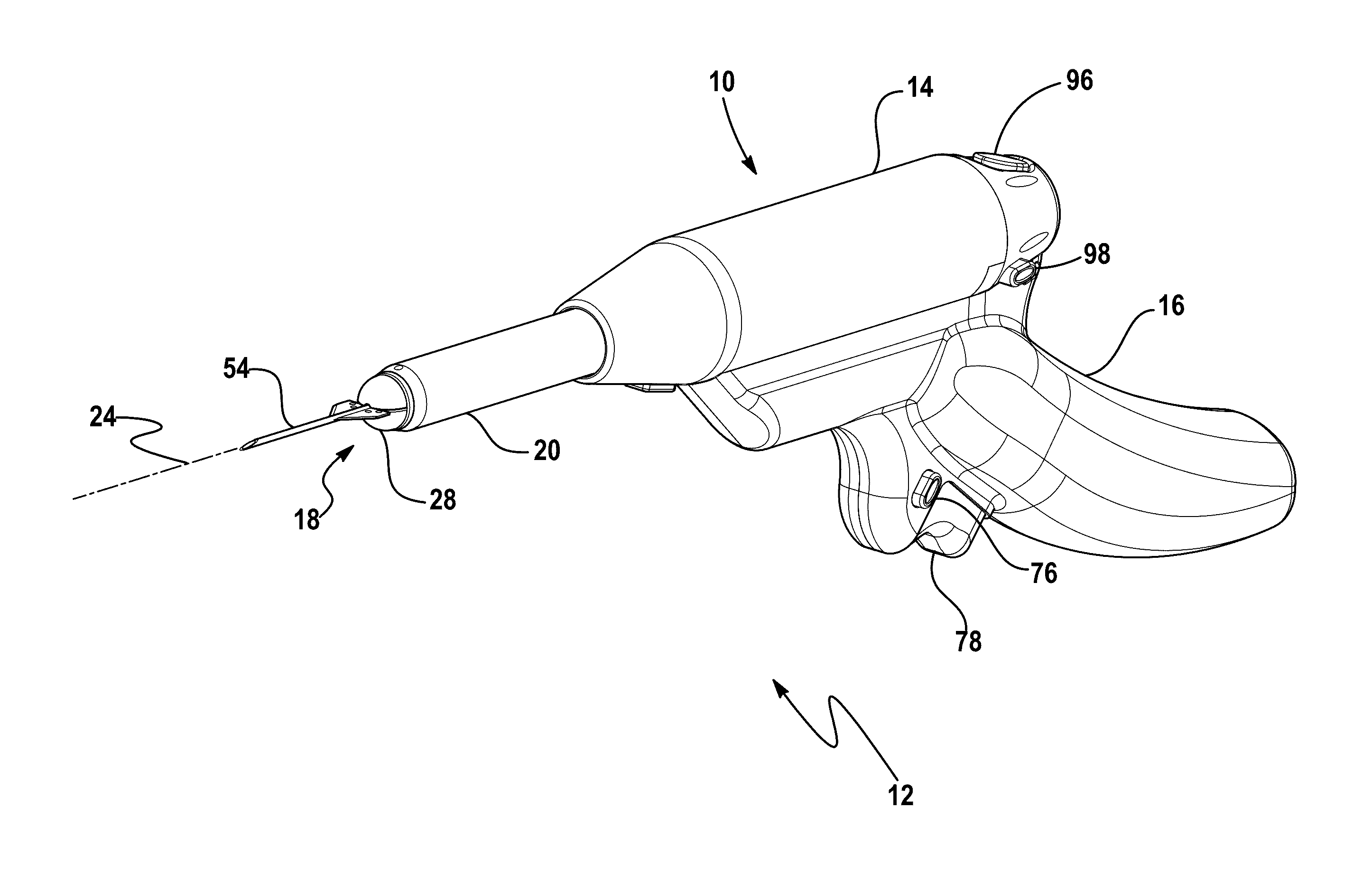
[0123]Referring to the Figures, wherein like numerals indicate like or corresponding parts throughout the several views, the present invention provides a device and method for allowing a surgeon to compress and support a breast from which a tissue sample may be excised.

[0124]An exemplary breast biopsy device 10 and a method of operating the breast biopsy device 10 are disclosed herein. With reference to FIG. 1, in one aspect of the present invention, the breast biopsy device 10 is embodied in a handheld device 12. It should be noted that the present invention may be embodied in a fixed device (not shown).

[0125]The handheld device 12 may include a housing 14 (see FIG. 10) and a handle 16. In one aspect, the housing 14 is removable from the handle 16. The handle 16 is reusable. The housing 14 (and all parts contained therein) are disposable and generally provided sterile. In one aspect of the present invention, the device 10 may include an integrated needle assembly 18 (described belo...


PUM


Abstract

Breast compression devices and methods of operating the same are disclosed. A first breast compression device comprises a back plate, a front paddle comprising two or more fingers, and an adjuster to adjust the space between the back plate and the front paddle. A second breast compression device comprises a back plate, a front paddle comprising two or more fingers, and a bar connecting the back plate and the front paddle. A method for compressing breast tissue with a breast compression device comprises wrapping the breast compression device around the breast tissue from any angle, the breast compression device including a back plate, a front paddle comprising two or more fingers, and a bar connecting the back plate and the front paddle, and adjusting the breast compression device to provide enough compression to render the breast tissue immobile.

Description

RELATED APPLICATIONS[0001]The present application claims priority to U.S. Provisional Patent Application Ser. No. 62 / 211,549, filed Aug. 28, 2015, hereby incorporated by reference.FIELD OF THE INVENTION[0002]The present invention relates generally to surgical instruments, and more particularly, to a breast compression device.BACKGROUND OF THE INVENTION[0003]Generally, to date there have been two coring type, excisional breast biopsy devices developed and marketed. These devices are described in the following U.S. Pat. Nos. 5,111,828; 5,197,484; 5,353,804; 6,080,113; 6,267,732; 6,383,145; 6,551,253; 5,782,775; 5,817,034; 5,857,982; 6,036,657; 6,077,231; 6,165,137; and 6,213,957, all of which are hereby incorporated by reference.[0004]These devices were originally developed for use with stereotactic imaging equipment. Generally, these devices use the same basic technology. The device disclosed in the '253 patent is exemplary. The biopsy device includes a localization needle with a gui...

Claims


Application Information

Patent Timeline
IPC IPC(8): A61B10/02
CPCA61B2010/0208A61B10/0266
Inventor FLATLAND, MARTIN L.
Owner SITESELECT INC
Why Eureka
Try Eureka