
DC plasma torch electrical power design method and apparatus

a plasma torch and electrical power technology, applied in the direction of plasma techniques, electrical devices, spark plugs, etc., can solve the problems of increasing raw material costs and energy resources, which are a substantial part of the cost of most if not all manufacturing processes, and achieve the effect of reducing voltage fluctuations, no arc extinguishing, and more stable operation of the torch

Inactive Publication Date: 2017-02-02
MONOLITH MATERIALS
View PDF13 Cites 19 Cited by
  • Summary
  • Abstract
  • Description
  • Claims
  • Application Information

AI Technical Summary

Benefits of technology

The patent describes a method for operating a DC plasma arc torch using a plasma forming gas and an operating voltage power supply. By using a power supply that is at least two times the average operating voltage, the torch operates more stably with reduced voltage fluctuations and no extinguishing of the arc. The patent also describes an apparatus comprising a DC plasma torch and an operating voltage power supply that is at least two times the average operating voltage used. Overall, the technical effect of this patent is improved stability and efficiency of operation for DC plasma arc torches.

Problems solved by technology

This can take the form of raw material costs, energy costs, or simple improvements in process stability and efficiencies, among other things.
In general, raw material costs and energy resources, which are a substantial part of the cost of most if not all manufacturing processes, tend to actually increase over time, because of scale up and increased volumes if for no other reasons.

Method used


Image

  • DC plasma torch electrical power design method and apparatus
  • DC plasma torch electrical power design method and apparatus
  • DC plasma torch electrical power design method and apparatus

Examples


example 1

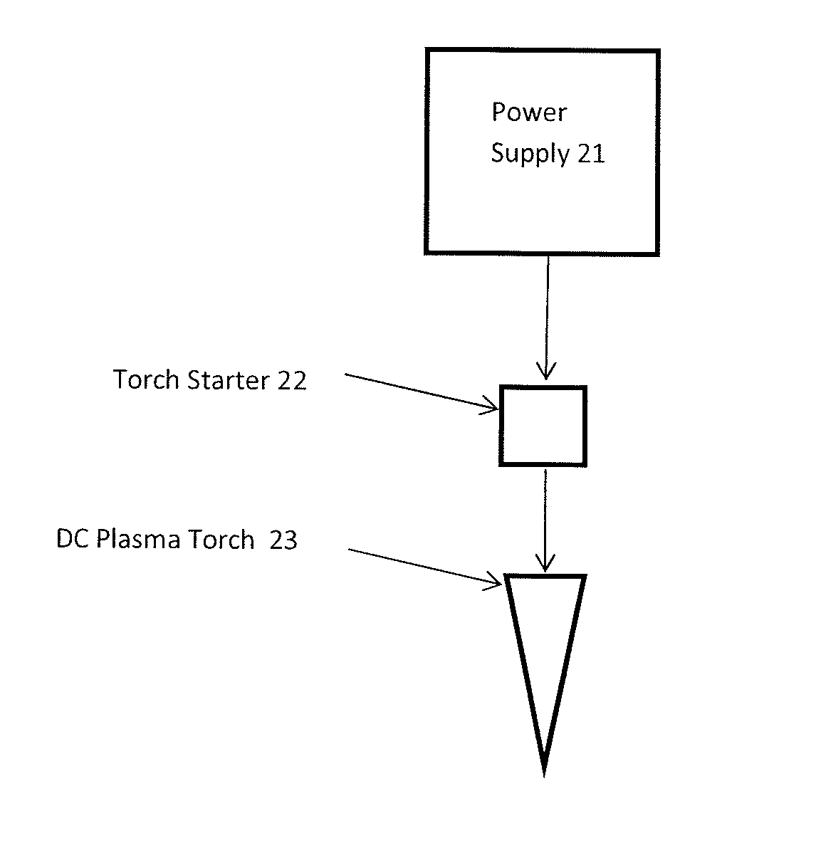
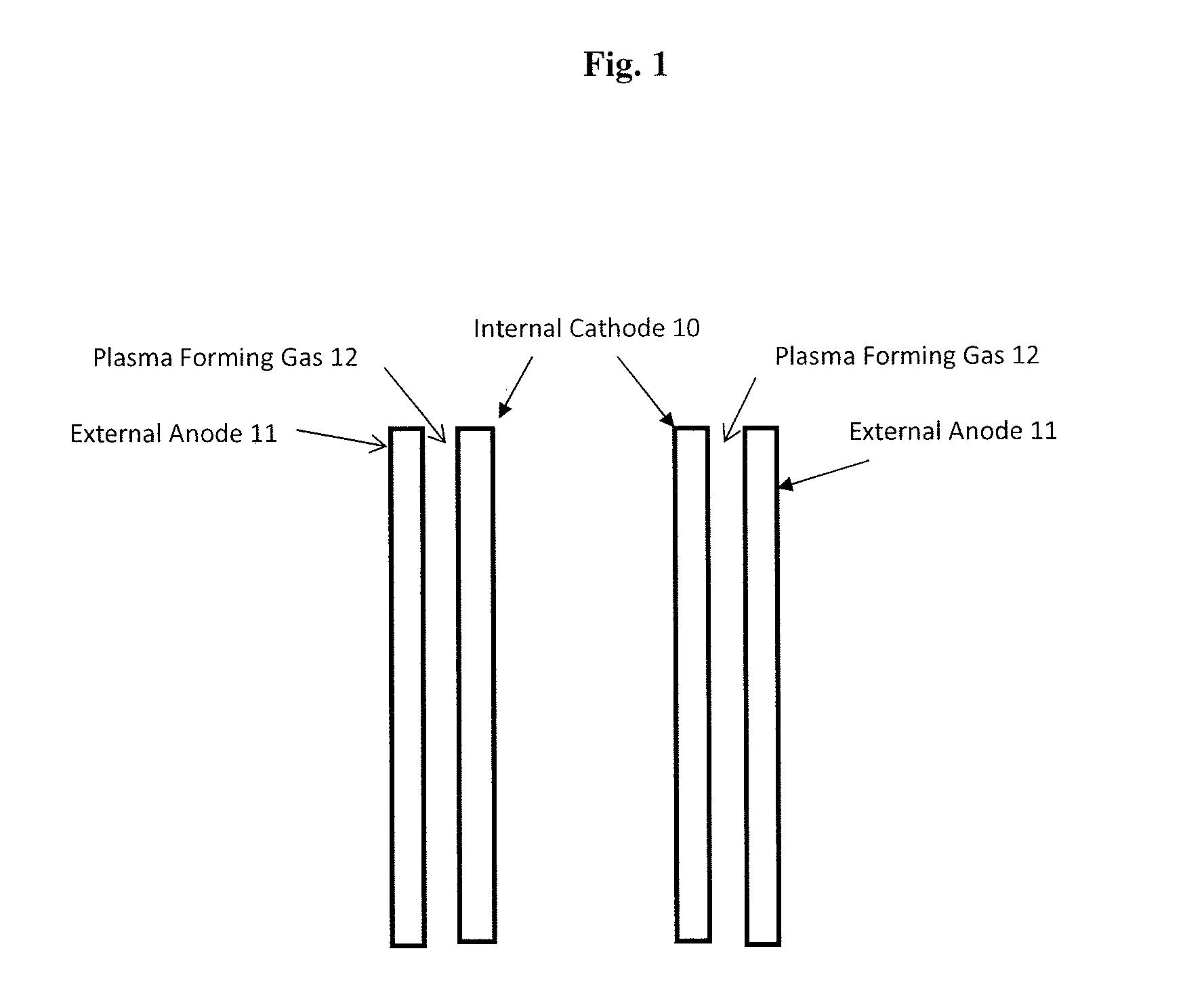
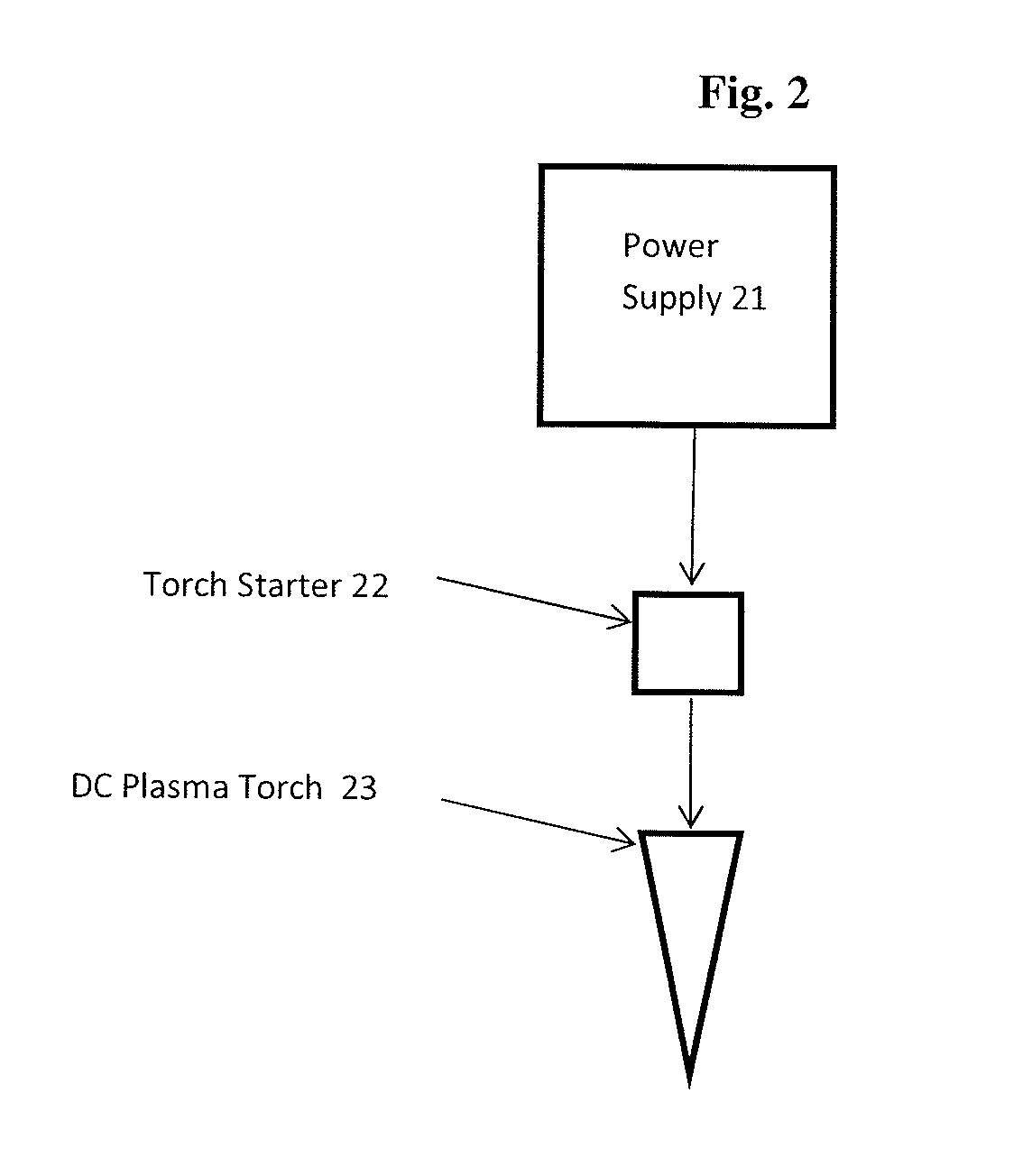
[0032]A DC concentric cylinder, graphite electrode, plasma torch is operated using an average operating voltage of 300-500 volts. The power supply to operate the plasma torch has a voltage generating capability of at least two times the average operating voltage needed, i.e. 1000 volts. This results in a much more stable operation of the torch as described herein. A separate starter power supply also has the capability of igniting the torch at a pulse voltage of at least 20 kilovolts. The starter power supply contains an appropriate amount of capacitive filtering to shunt unwanted energy away from sensitive electronic components.

example 2

[0033]A topology for implementing the system described in Example 1 is as follows. A 6, 12, 18, or 24-pulse rectifier is used as the front end AC-DC converter. This rectifier can be phase-controlled or naturally commutated, with a capacitive output filter, and with or without a commutating output choke. Several chopper regulators composed of power electronic switching devices, snubber circuits, and gating control circuits are used to control the current applied to the load. These chopper regulators can be placed in a parallel configuration to add redundancy, or in a series-parallel configuration to also allow for the use of devices with lower blocking voltages. Smoothing reactors are used as the main energy storage device in the current regulator, and are distributed among the positive and negative legs of the regulator to add additional protection for the sensitive power electronics. Capacitors are used as filters on the output of the current regulator to absorb high frequency ener...


PUM


Abstract

A method and apparatus for operating a DC plasma torch. The power supply used is at least two times the average operating voltage used, resulting in a more stable operation of the torch. The torch can include two concentric cylinder electrodes, the electrodes can be graphite, and the plasma forming gas can be hydrogen. The power supply provided also has the capability of igniting the torch at a pulse voltage of at least 20 kilovolts.

Description

CROSS-REFERENCE TO RELATED APPLICATIONS[0001]This application claims priority to U.S. Provisional Application No. 62 / 198,431, filed Jul. 29, 2015, which application is incorporated by reference herein in its entirety.TECHNICAL FIELD[0002]The field of art to which this invention generally pertains is methods and apparatus for making use of electrical energy to effect chemical changes.BACKGROUND[0003]No matter how unique the product or process is, over time, all manufacturing processes look for ways to become more efficient and more effective. This can take the form of raw material costs, energy costs, or simple improvements in process stability and efficiencies, among other things. In general, raw material costs and energy resources, which are a substantial part of the cost of most if not all manufacturing processes, tend to actually increase over time, because of scale up and increased volumes if for no other reasons. For these, and other reasons, there is a constant search in this ...

Claims


Application Information

Patent Timeline
IPC IPC(8): H05H1/36
CPCH05H2001/3431H05H1/36H01T13/00H05H1/473H05H1/2443H05H1/3431
Inventor MOSS, JOHN JAREDNOEL, BRIAN T.
Owner MONOLITH MATERIALS
Learn More