Aircraft wing with a wing tip device and a strut
a technology of wing tip and strut, which is applied in the direction of airflow influencers, wing adjustments, aircraft stabilisation, etc., can solve the problems of difficult to efficiently distribute the load generated by the wing tip device during use, add weight and/or complexity to the retrofitting or forward-fitting process of the wing tip device, and the scope of modifying the structure of the wing is often very limited, so as to achieve fewer structural modifications and facilitate weight saving. ,
- Summary
- Abstract
- Description
- Claims
- Application Information
AI Technical Summary
Benefits of technology
Problems solved by technology
Method used
Image
Examples
first embodiment
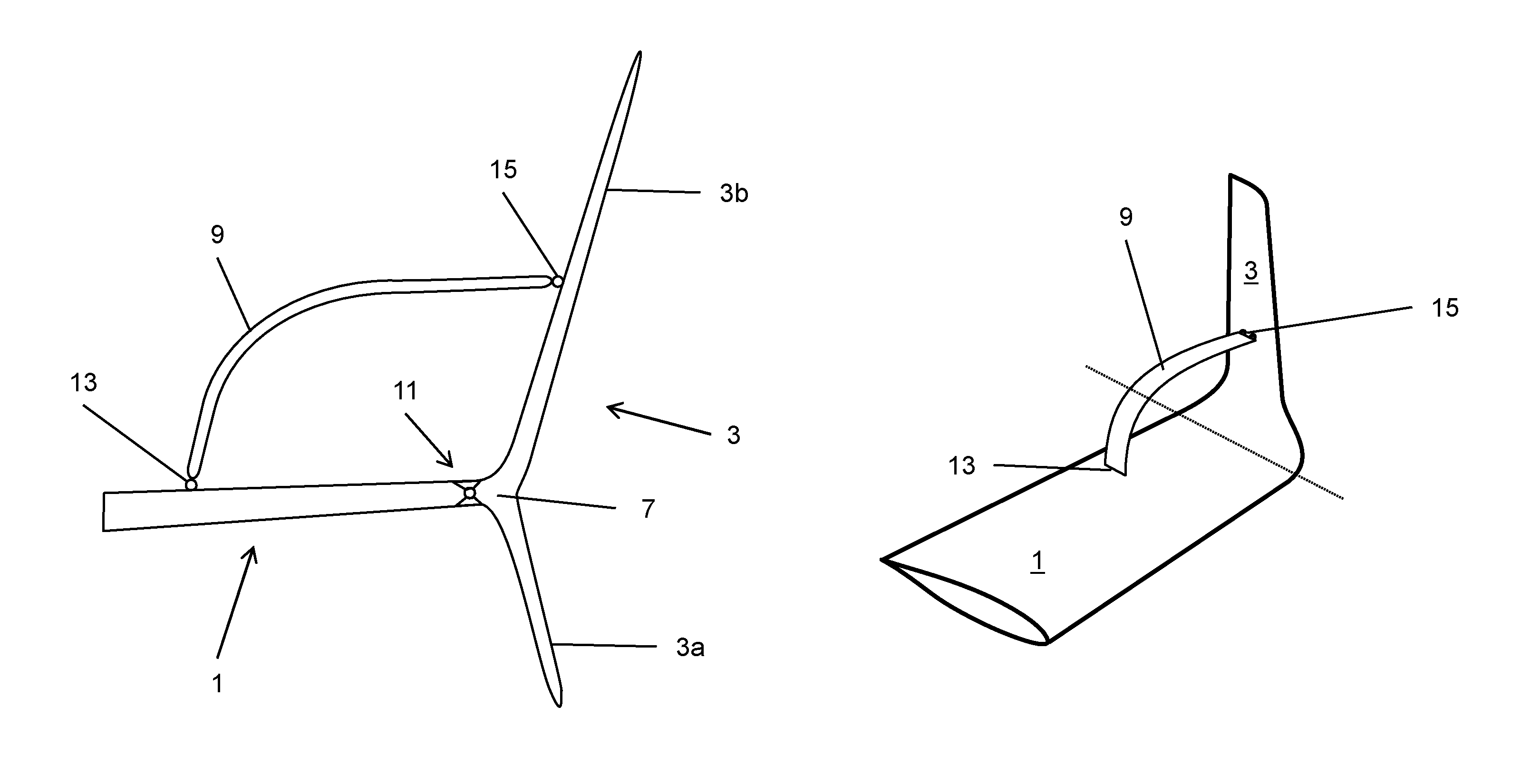
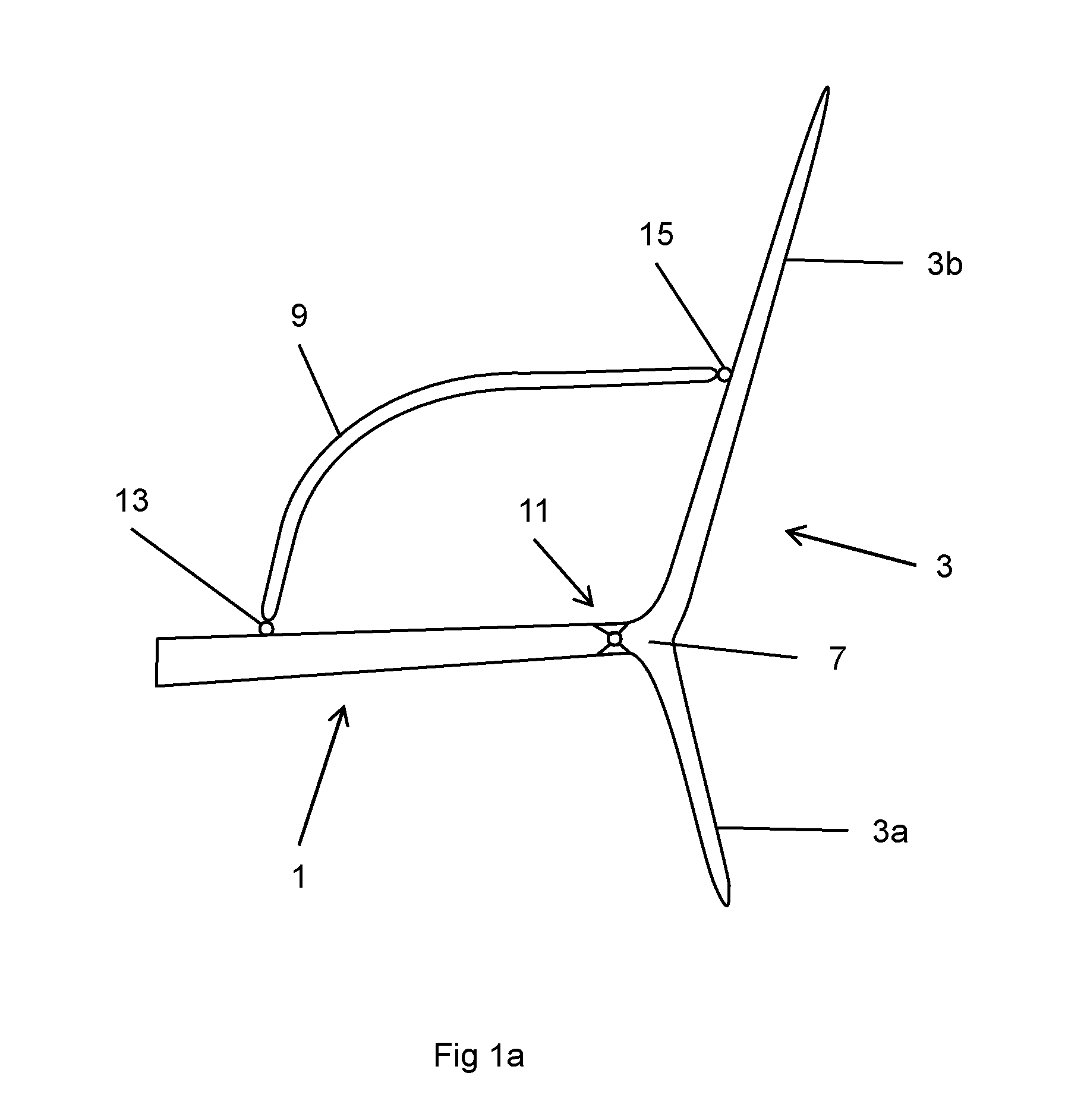
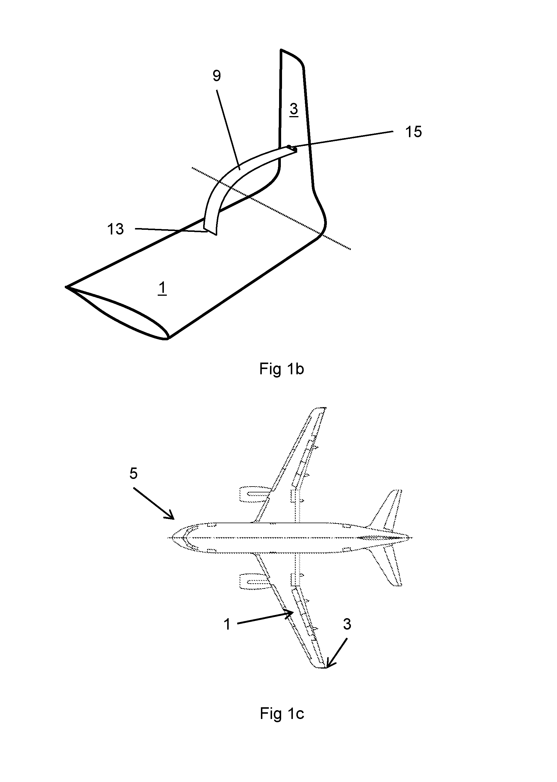
[0048]In contrast to known arrangements, the wing tip device 3 in the first embodiment is braced by an external strut 9 extending from a second joint 13 on the wing 1 to third joint 15 approximately mid-way along the upwardly extending part 3b of the wing tip device 3. The strut 9 transfers the majority of aerodynamic loadings on the wing tip device (generated during use) to the wing 1. The loadings are transferred to the wing 1 at the second joint 13. Thus, by virtue of the strut 9, the loadings that would normally be reacted through the joint at the wing tip / wing tip device root, are instead transferred to a location further inboard on the wing 1.
[0049]Such an arrangement has a number of benefits from a structural perspective. In particular, the wing box at the inboard location on the wing 1 below the second joint 13 is relatively thick (compared to the thickness of the box at the wing tip). This means the wing box is better able to cope with the loading and requires minimal struc...
fourth embodiment
[0059]FIG. 12 shown the arrangement of the invention (FIG. 4) but wherein the wing tip device 1209 is arranged to rotate to reduce the span. Such a span reduction is especially pronounced (for a given angular rotation) when using the planar wing extension 1203b.
[0060]FIGS. 13a to 13c are schematics showing some further embodiments of the invention in which a wing tip device 1303 is braced by the strut 1309 to transfer loads into the wing 1301 at a location inboard of the wing tip root 1307.
[0061]FIGS. 14a and 14b are schematics showing some further embodiments of the invention in which a wing tip device 1403 is braced by the strut 1409 to transfer loads into the wing 1401 at a location inboard of the wing tip root 1407. In both these embodiments, the wing comprises a stub 1417 connected to a wing rib (not shown). The stub 1417 facilitates a straightforward connection to the strut 1409. This is a particularly attractive embodiment when the wing tip device 1403 is being forward-fitte...
PUM
 Abstract
Description
Claims
Application Information
 - R&D
- Intellectual Property
- Life Sciences
- Materials
- Tech Scout
- Unparalleled Data Quality
- Higher Quality Content
- 60% Fewer Hallucinations
Browse by: Latest US Patents, China's latest patents, Technical Efficacy Thesaurus, Application Domain, Technology Topic, Popular Technical Reports.
© 2025 PatSnap. All rights reserved.Legal|Privacy policy|Modern Slavery Act Transparency Statement|Sitemap|About US| Contact US: help@patsnap.com


