NxN PARALLEL OPTICAL TRANSCEIVER

a parallel optical and transceiver technology, applied in electromagnetic transceivers, optical waveguide light guides, instruments, etc., can solve the problems of large loss(es) at 850 nm, difficult to overcome, and difficult design, etc., and achieve the effect of smooth light focus

Active Publication Date: 2017-01-26
SOURCE PHOTONICS CHENGDU
View PDF5 Cites 3 Cited by
  • Summary
  • Abstract
  • Description
  • Claims
  • Application Information

AI Technical Summary

Benefits of technology

[0009]The GRIN lenses may each comprise a cylindrical optical lens having a refractive index that varies along its radial axis, and the GRIN lenses may smoothly focus the light from laser devices to the multimode fiber array, as well as from the multimode fiber array to the photodiode array.

Problems solved by technology

As limited by the material(s) and the manufacturing technique(s), VCSELs are suitable for a waveband of 850 nm, but use at other wavelengths or wavebands has met challenges that have been difficult to overcome.
Standard fiber transmission at 850 nm brings large loss(es) such that conventional parallel optical transceivers having VCSELs are used primarily for short-distance transmission within a range of about 300-500 meters, far below the requirement for data transmission and PONs (Passive Optical Networks).
This design is relatively complicated, and appears to be limited to a parallel optical transmitter for a short-distance transmission (less than 300 meters).
Moreover, this optical link design does not appear to be broadly applied or adapted.

Method used


Image

  • NxN PARALLEL OPTICAL TRANSCEIVER
  • NxN PARALLEL OPTICAL TRANSCEIVER
  • NxN PARALLEL OPTICAL TRANSCEIVER

Examples


first embodiment

A First Embodiment

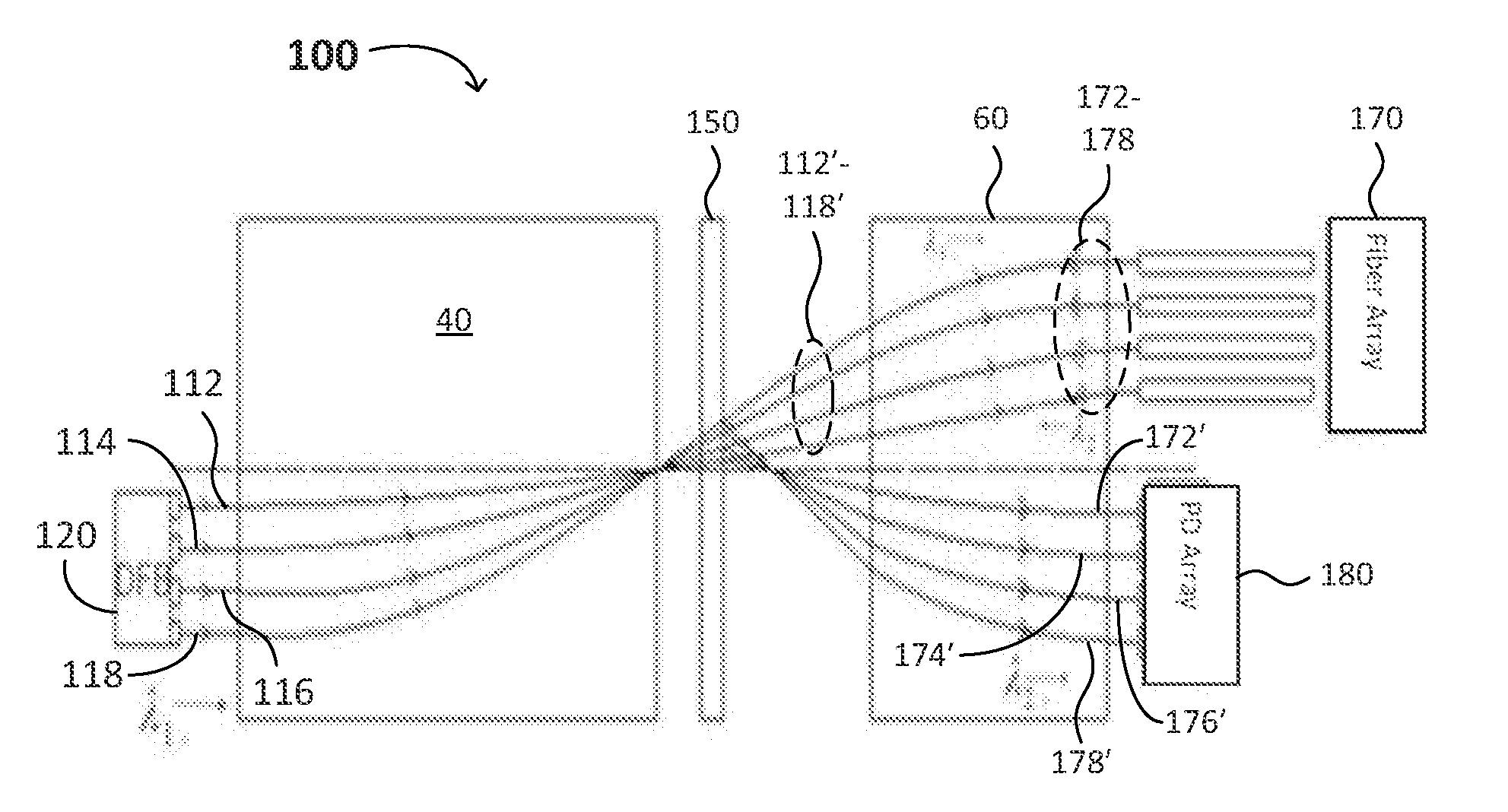
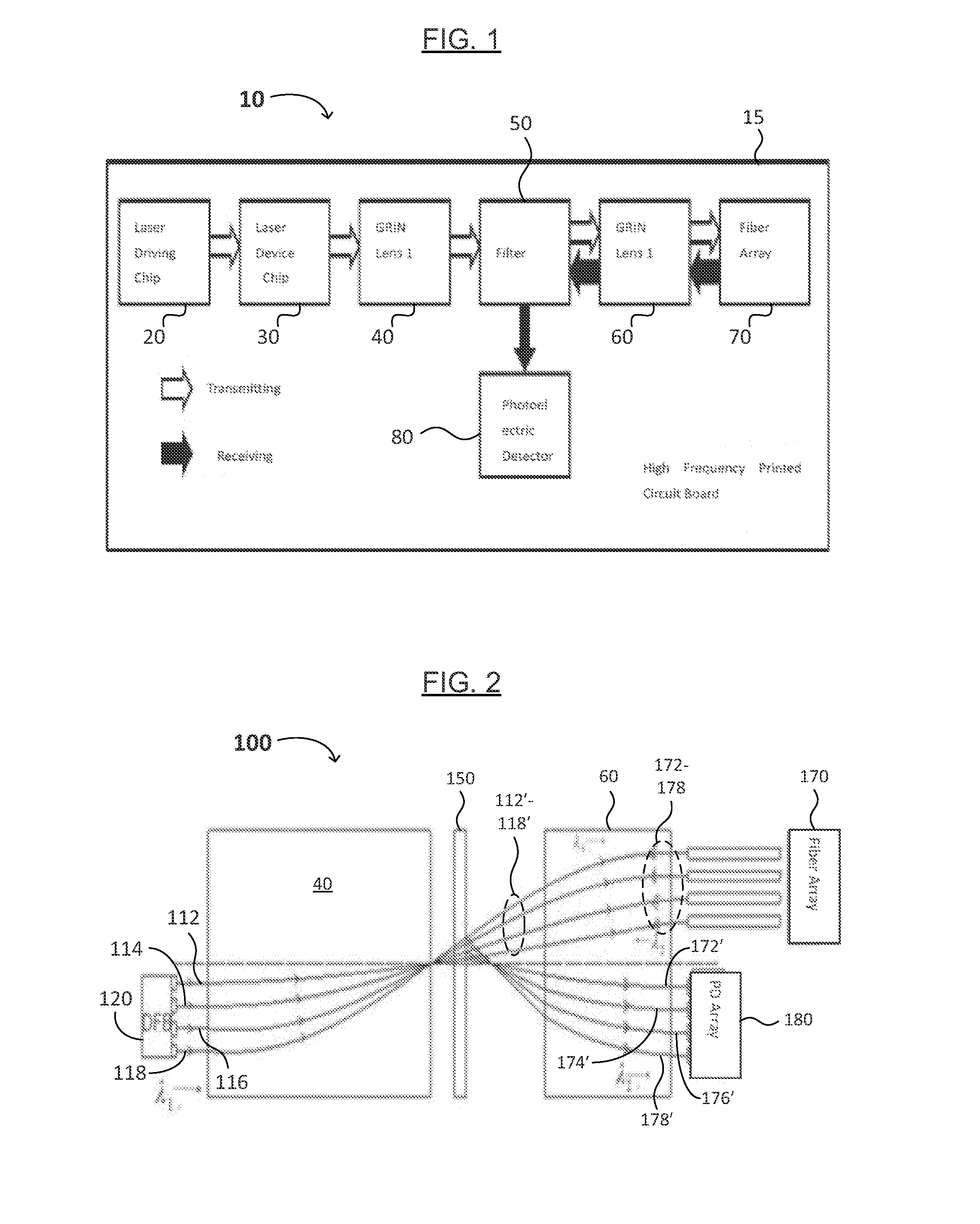
[0030]FIG. 2 illustrates an exemplary optical link 100 of the parallel optical transceiver (e.g., optical transceiver 10) in accordance with embodiments of the present invention. In the optical link at the transmitting end (e.g., the transmitter), laser beams 112-118 having the same wavelength λ1 are emitted from a plurality of (e.g., 4) DFB laser chips 120 at the same time (e.g., simultaneously). The laser beams 112-118 are first focused by the first GRIN lens 40, then they pass through a wavelength-selective band-pass filter 150. The multiple (e.g., 4) focused laser beams 112′-118′ are refocused by the second GRIN lens 60, then the refocused beams respectively enter the channels (e.g., 4 channels) in the fiber array 170.

[0031]In the optical link at the receiving end (e.g., the receiver), multiple (e.g., 4) laser beams 172-178 having the same wavelength λ2 from the four channels in the fiber array 170 are focused by the second GRIN lens 60 and reflected by the sur...

second embodiment

A Second Embodiment

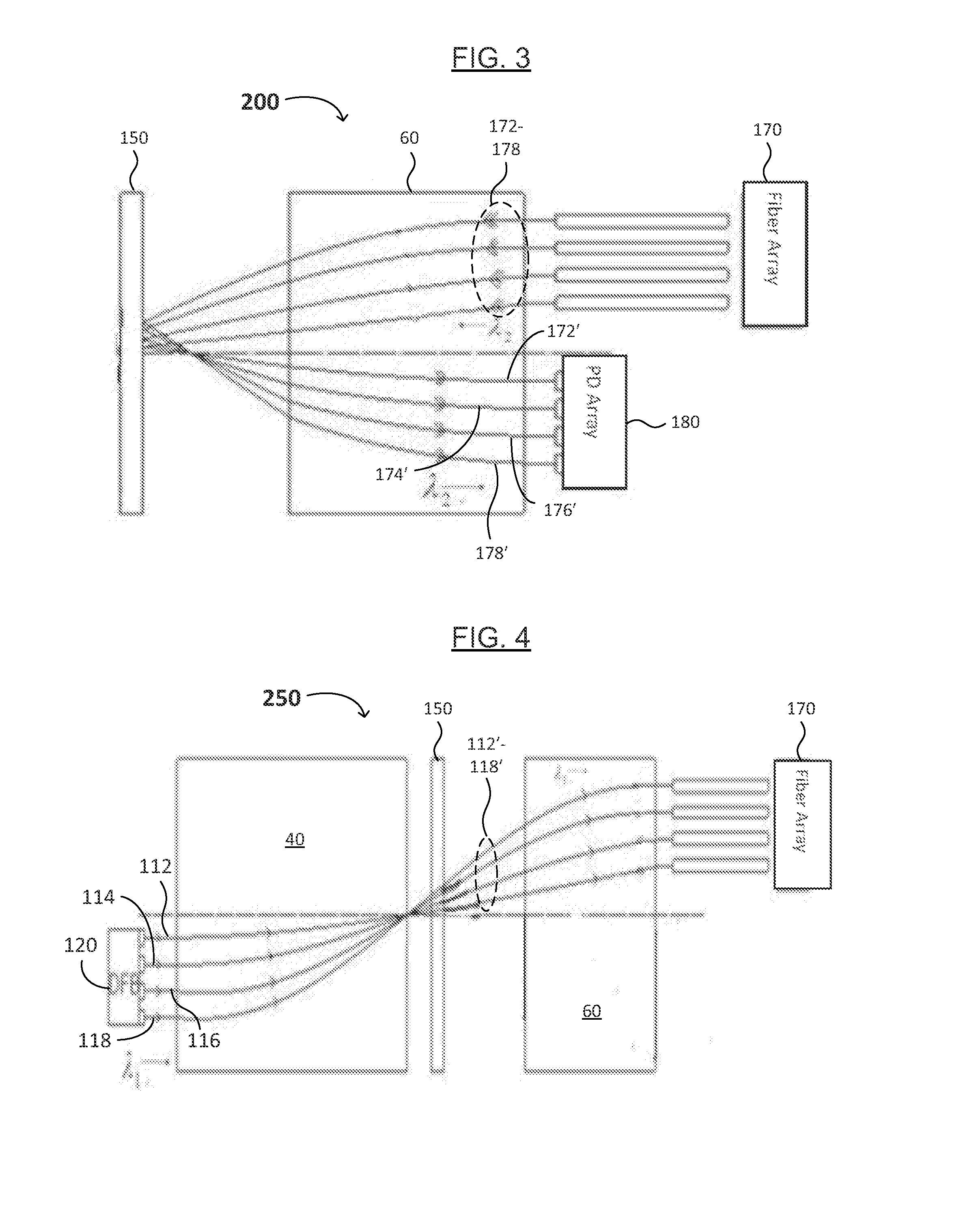
[0036]FIG. 3 illustrates an exemplary optical link of the parallel optical transceiver in accordance with embodiments of the present invention. In the parallel optical transceiver, or as shown in FIG. 3, a receiver 200, 4 laser beams 172-178 having the same wavelength λ2 from the four channels in the fiber array 170 are focused by the second GRIN lens 60 and reflected by the surface of the wavelength-selective and / or bandpass filter 50, and then the 4 reflected laser beams 172′-178′ are refocused by the second GRIN lens 60 and enter the PD chip array 180. As above, in embodiments of the present invention related to a FP laser, the only difference is that each DFB laser chip is replaced by a FP laser chip, so there is no more tautology.

third embodiment

A Third Embodiment

[0037]FIG. 4 illustrates an exemplary optical link of the parallel optical transceiver in with embodiments of the present invention. In the parallel optical transceiver, or as shown in FIG. 4, a transmitter 250, laser beams 112-118 having the same wavelength λ1 emitted simultaneously from 4 DFB laser chips 110 are first focused by the first GRIN lens 40, then pass through the band pass filter 50, then the 4 laser beams are refocused by the second GRIN lens 60. After that, the beams respectively enter the 4 channels in the fiber array 170.


PUM


Abstract

An N×N parallel optical transceiver includes a printed circuit board, a laser driving control chip, one or more lasers, two GRIN lenses, an optical band-pass filter, a multimode fiber array and a photodiode array. In the transmitter, laser beams of the same wavelength simultaneously output from the laser chip are first focused by the first GRIN lens, then the beams pass through a wavelength band-pass filter and are refocused by the second GRIN lens, and enter the channels in the multimode fiber array. In the receiver, laser beams of a different wavelength from the multimode fiber array are focused by the second GRIN lens, then reflected by the band-pass filter, refocused by the second GRIN lens, and received by the photodiode array. The multi-channel parallel transceiver has a small form, and can integrate a DFB or FP laser chip and GRIN lenses.

Description

FIELD OF THE INVENTION[0001]The present invention generally relates to the field of (optical) fiber communication. More specifically, embodiments of the present invention pertain to parallel optical transceivers, methods of making and using the same, and systems including the same.DISCUSSION OF THE BACKGROUND[0002]As one implementation of high speed optical transmission, an advantage of parallel optical transceiving (e.g., optical signal transmission and reception) lies in technology and cost. Parallel optical transceiving utilizes intermediate, high speed photoelectric technology and repeating (e.g., multiple) channels to achieve a high speed, large capacity transmission. Particularly, in short-distance communication, such as interconnection between backplanes in a large communication system and data transmission within a local area network, parallel optical transceiving is characterized in that it has a high transmission speed, small size, low weight, low crosstalk, etc. Driven by...

Claims


Application Information

Patent Timeline
Patent Type & Authority Applications(United States)
IPC IPC(8): G02B6/42G02B6/32G02B6/12H04B10/40
CPCG02B6/4246H04B10/40G02B6/428G02B6/4215G02B6/32G02B2006/12123G02B6/4292G02B6/12004G02B6/4279G02B2006/12121G02B6/4206G02B6/4207G02B6/425G02B6/43
Inventor XU, YUANZHONGMAO, JINGLEIWANG, QIANGWU, KUI
Owner SOURCE PHOTONICS CHENGDU
Why Eureka
Try Eureka