
Torsional Vibration Damper Comprising A Damping System, A Damping Device And A Ground Device

a torsional vibration and damper technology, applied in fluid gearings, couplings, fluid gearings, etc., can solve the problems of sharp decline of deflection angles at the output of the damping device, significant rise in rotational irregularities at higher speeds, and increase in rotational irregularities, so as to reduce the stiffness and reduce the stiffness of the energy storage

Active Publication Date: 2017-01-26
ZF FRIEDRICHSHAFEN AG
View PDF2 Cites 8 Cited by
  • Summary
  • Abstract
  • Description
  • Claims
  • Application Information

AI Technical Summary

Benefits of technology

The patent is about a device that reduces vibrations in a rotating machine. The device has two parts that are connected to each other by a connection arrangement. By separating the connection points, the device can be made more compact in the axial direction. The mass arrangement engages with the mass carrier of the device using a holder and riveted joint, while the mass carrier connects to the output using a similar joint. This design helps to minimize the space needed for the device and makes it more efficient in reducing vibrations.

Problems solved by technology

In conflict with this advantage, however, is the fact that there is a significant rise in rotational irregularity at higher speeds, for example, within a speed range of 1,500 to 1,800 revolutions per minute.
This rise in rotational irregularity is accompanied by sharply declining deflection angles at the output of the damping device even when torsional vibrations are present at the input of the damping device.
It is particularly disadvantageous for the output of the damping device to persist in a vibration node because this would dispense with the vibration excitations which are vital for the functioning of damper masses of the mass damper system connected to the output of the damping device.

Method used


Image

  • Torsional Vibration Damper Comprising A Damping System, A Damping Device And A Ground Device
  • Torsional Vibration Damper Comprising A Damping System, A Damping Device And A Ground Device
  • Torsional Vibration Damper Comprising A Damping System, A Damping Device And A Ground Device

Examples


Embodiment Construction

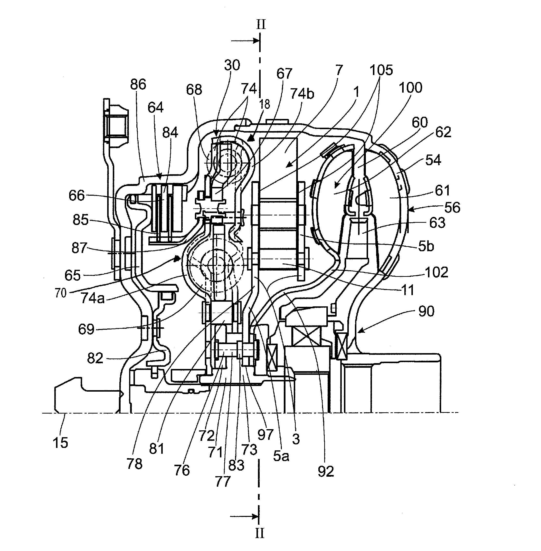
[0020]FIG. 1 shows a coupling arrangement 56 which has a housing 54 and, since it is constructed as a hydrodynamic torque converter 90, a hydrodynamic circuit 60 with impeller 61, turbine 62 and stator 63. Further, a clutch device 64 is provided which is formed with a clutch piston 65 and with a friction disk clutch 66, wherein radially outer friction disk elements 84 of the friction disk clutch 66 are in toothed engagement with an outer wall 86 of the housing 54 and radially inner friction disk elements 85 of the friction disk clutch 66 are in toothed engagement with a friction disk element carrier 87 which engages at an input 67 of a damping device 70. Depending on the control of the clutch piston 65 which is arranged on a piston carrier 82 so as to be axially displaceable, the clutch device 64 is movable between an engagement position and a release position. The input 67 of the damping device70 is connected via a first damping unit 68 to an intermediate transmission 74 which has ...


PUM


Abstract

A torsional vibration damper (70) with a damping device which has an input (67) and an output (72) which is operatively connected to a driven side (73). The output is connected to a mass damper system (1) and also to a mass arrangement (100). One of the two subassemblies—i.e., mass damper system (1) and mass arrangement (100)—which are connected to the output (72) of the damping device (70) engages at the respective other subassembly comprising mass damper system or mass arrangement which is in turn connected to the output by a connection arrangement (77).

Description

PRIORITY CLAIM[0001]This is a U.S. national stage of application No. PCT / EP2015 / 055904, filed on Mar. 20, 2015. Priority is claimed on the following application: Country: Germany, Application No.: 10 2014 207 258.1, the content of which is incorporated herein in its entirety by reference.FIELD OF THE INVENTION[0002]The present invention is directed to a torsional vibration damper with a damping device which has an input and an output which is operatively connected to a driven side, and the output is connected to a mass damper system and also to a mass arrangement.BACKGROUND OF THE INVENTION[0003]A torsional vibration damper of the type mentioned above can be seen from US20140090514in FIG. 3. This torsional vibration damper is provided for a hydrodynamic coupling arrangement having a hydrodynamic circuit formed by an impeller, a turbine and a stator. The input of the torsional vibration damper is operatively connected to a drive such as an internal combustion engine via a clutch devi...

Claims


Application Information

Patent Timeline
Patent Type & Authority Applications(United States)
IPC IPC(8): F16F15/14F16H45/02F16D3/12
CPCF16F15/145F16D3/12F16H2045/0284F16H2045/0226F16H2045/0263F16H45/02F16F15/12346F16H2045/021F16H2045/0231
Inventor HERTEL, MARTINWINTERSTEIN, MICHAELSUDAU, JORG
Owner ZF FRIEDRICHSHAFEN AG
Learn More