
Rope End-Fastening Method, Rope with End Fastener, and End Fitting for Use in Rope End-Fastening Method

Active Publication Date: 2017-01-26
TOKYO ROPE MFG +1
View PDF0 Cites 6 Cited by
  • Summary
  • Abstract
  • Description
  • Claims
  • Application Information

AI Technical Summary

Benefits of technology

The present invention provides a way to securely and easily prevent the withdrawal of a rope while preventing concentration of stress on the rope. This is achieved through the use of a terminal metal fitting with a through hole and a diameter-enlarging member that constrains the rope. No expansive filler is needed, which simplifies the construction process and reduces working hours.

Problems solved by technology

However, some ropes may sometimes fall off the terminal fixing tool when a tensile load is applied to the ropes, because the fastening power by the terminal fixing tool is weakened due to the diameter reduction of the ropes.
Further, as for the high-strength fiber composite cable, while it has high strength comparative to a PC steel strand wire when tensioned in an axial direction, it is vulnerable to a surface flaw, the local shearing force in a diametrical direction, and so on.
Thus, in attaching the terminal fixing tool to the rope, a fixing method by directly inserting a wedge, which may be employed as a normal method for fixing a PC steel strand wire, easily causes cutting of the rope due to the shear failure, and as a result, high fixing efficiency cannot be achieved.

Method used


Image

  • Rope End-Fastening Method, Rope with End Fastener, and End Fitting for Use in Rope End-Fastening Method
  • Rope End-Fastening Method, Rope with End Fastener, and End Fitting for Use in Rope End-Fastening Method
  • Rope End-Fastening Method, Rope with End Fastener, and End Fitting for Use in Rope End-Fastening Method

Examples


Embodiment Construction

[0036]Embodiments of the present invention are described below with reference to the drawings.

[0037]A rope as used herein includes one which is formed by parallelizing or twisting a plurality of wires together, regardless of materials. The rope as used herein also includes a rope formed by twisting a plurality of wires together into a strand and then twisting a plurality of strands.

[0038]The rope as used herein further includes one which is formed by impregnating a single wire, or a plurality of wires twisted together into a single wire, with resin to make a composite and twisting a plurality of wires each made from the composite. A surface of the composite may be wrapped, for example, by being covered with fibers to have a blade shape, covered by resin, or have fibers wrapped therearound before twisting.

[0039]Specific examples of the rope include, for example, a rope formed from high-elasticity fibers such as synthetic fibers illustrated as rubber, nylon, and Tetoron; a high-streng...


PUM


Abstract

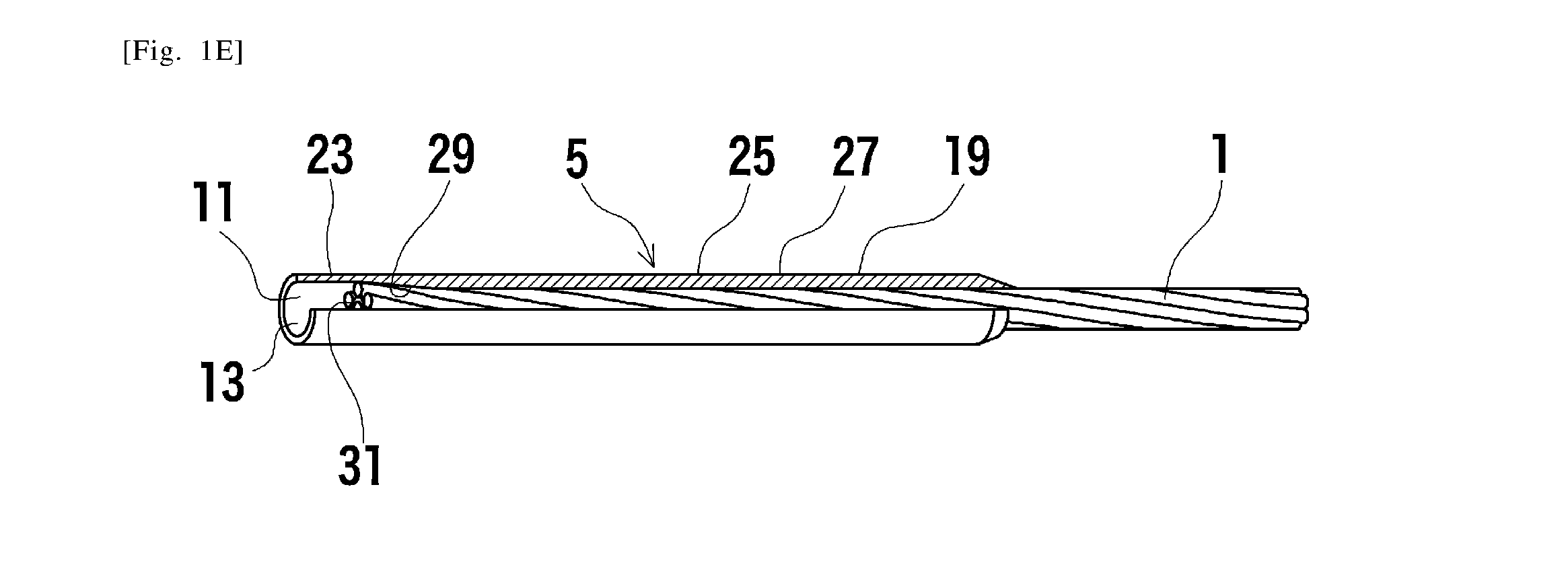
A rope terminal fixing method is provided, which may be used easily at a construction site, causes less shearing load, and may reliably prevent the falling-off of the rope.The rope terminal fixing method comprises the following steps. A tubular terminal metal fitting which comprises a proximal opening, a distal opening, and a through hole communicating the proximal and distal openings is prepared. A terminal of a rope is inserted through the proximal opening into the through hole, a portion of the terminal of the rope extended from the distal opening is loosened, and a diameter-enlarging member is fixed to a core wire of the rope. Then, the terminal of the rope is brought back into the through hole. A fixed width portion extending in an axial direction of the terminal metal fitting is pressed from the outside in a circumferential direction by swaging, such that a protrusion constraining the rope so as to reduce its diameter is formed in the through hole. The diameter-enlarging member cooperates with an end of the protrusion located on the distal opening side to constrain surrounding wires other than the core wire in a sandwiching manner. A rope with terminal fixing tools, which comprises the terminal fixing tools attached thereto by this method, is also provided.

Description

TECHNICAL FIELD[0001]The present invention relates to a rope terminal fixing method and a rope with terminal fixing tools. In particular, the present invention relates to a rope terminal fixing method which may be implemented easily even at a construction site; a rope with terminal fixing tools, which comprises the terminal fixing tools attached thereto by this method; and a terminal metal fitting used in the rope terminal fixing method.BACKGROUND ART[0002]Generally, ropes are widely used in, for example, the mooring of ships, or car coupling. In particular, since a strand wire rope as a high-strength fiber composite cable such as a carbon fiber composite cable has characteristics such as high strength, light weight, high corrosion resistance, and a non-magnetic property, it has been used as, for example, a reinforcing material for a concrete structure such as a pier or a prestressed concrete bridge in a corrosive environment; a tensile material for a high corrosion resistant ground...

Claims


Application Information

Patent Timeline
IPC IPC(8): D07B9/00F16G11/02
CPCF16G11/02D07B9/00F16C1/145F16G11/05
Inventor FUKUDA, YASUYUKIKOSE, NORIAKI
Owner TOKYO ROPE MFG
Learn More