
System comprising a closed-circuit respirator and a monitoring device therefor

a closed-circuit respirator and monitoring device technology, applied in the field of systems comprising closed-circuit respirators and monitoring devices therefor, can solve the problems of reducing the theoretically possible maximum service life, increasing the amount of breathing gas removed, and inefficient, so as to achieve the effect of prolonging the use tim

Inactive Publication Date: 2017-01-26
DRAGER SAFETY
View PDF3 Cites 3 Cited by
  • Summary
  • Abstract
  • Description
  • Claims
  • Application Information

AI Technical Summary

Benefits of technology

The present invention is a closed-circuit respirator with a monitoring device that allows for longer use time. It provides information about how much oxygen is consumed or still available for further use. The system ensures a minimum dispensing rate of 1.6 L / minute and prevents excess breathing gas from being released due to a leak. By using a low oxygen concentration for a longer time, the respirator user can breathe in a closed circuit for a longer period of time compared to conventional systems.

Problems solved by technology

When the respirator user has a higher respiratory minute volume due to increased strain, the excess breathing gas demand is covered from the breathing bag, which is loaded with a spring and collapses as a result as the amount of breathing gas removed increases.
However, this is not efficient, because unused oxygen is lost to the ambient atmosphere as a result, and this is no longer available for the user of the closed-circuit respirator and thus reduces the theoretically possible maximum service life.
It happens in many applications that the respirator user has a markedly lower oxygen demand than the fixed preset value of 1.6 L / minute, but in case of a preset quantity of 400 L of oxygen in the oxygen tank, this nevertheless leads to a limitation of the duration of use to about 250 minutes because the quantity of breathing lime is selected according to the quantity of oxygen being carried along.

Method used


Image

  • System comprising a closed-circuit respirator and a monitoring device therefor

Examples


Embodiment Construction

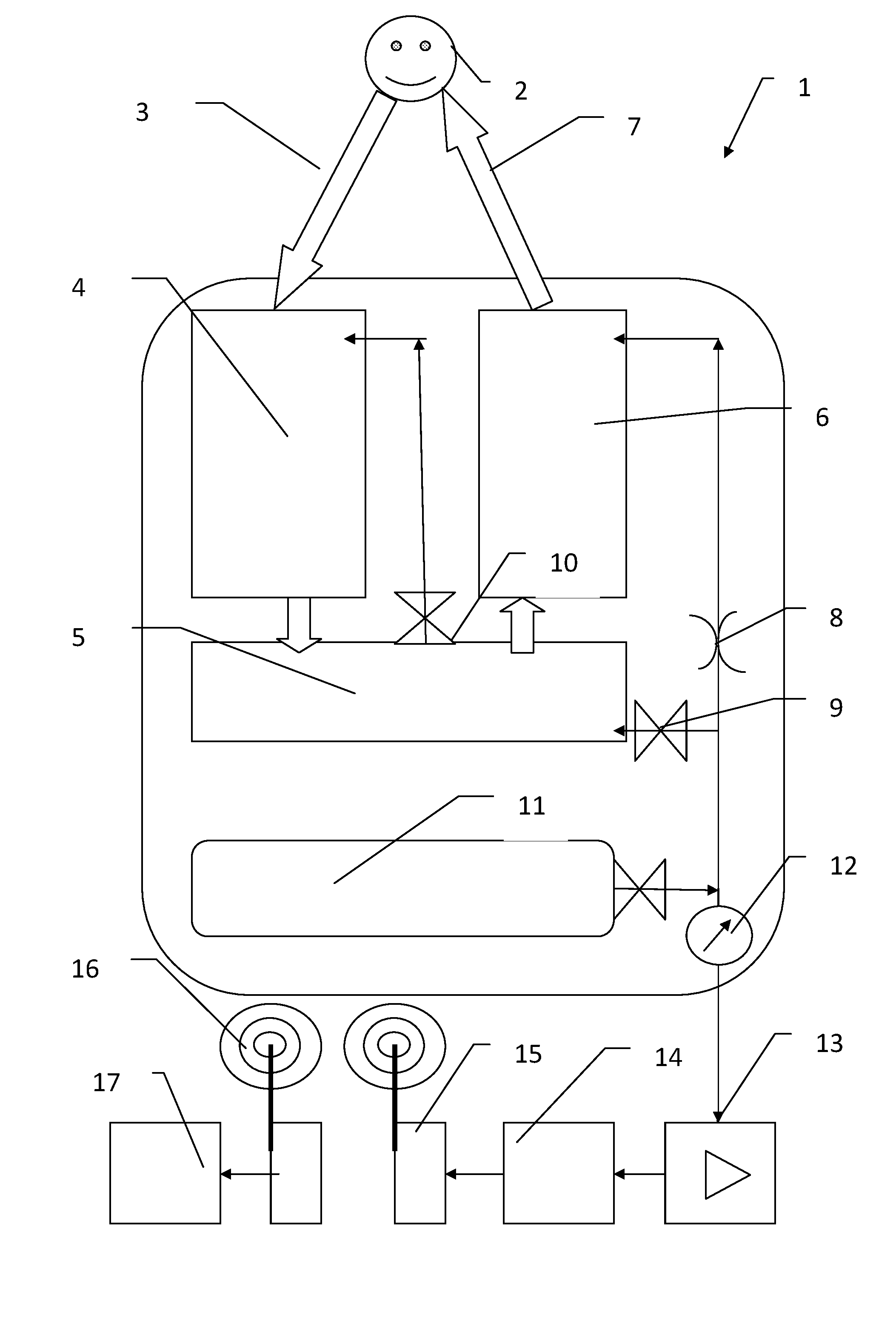
[0051]Referring to the drawings, the closed-circuit respirator 1 with the monitoring device has a breathing mask 2, from which the closed breathing circuit leads farther first through an exhalation tube 3 to a breathing lime cartridge 4 as a CO2 absorber. The counter-lung is established by means of a spring-loaded breathing bag 5 and the breathing gas flows through the breathing bag 5 and farther to a breathing gas cooler 6, in which the breathing gas heated in the breathing lime cartridge 4 is cooled again. The closed breathing circuit then closes via an inhalation tube 7, which leads back to the breathing mask 2. The breathing gas cooler may be present, as it is in this exemplary embodiment, but it is not necessary for the present invention.

[0052]Oxygen is dispensed constantly in the inhalation line via a constant dispensing unit 8. If the quantity of oxygen fed is not sufficient or breathing gas is lost due to leakage, the spring-loaded breathing bag 5 collapses and actuates a mi...


PUM


Abstract

A system includes a closed-circuit respirator (1) with a breathing mask (2), a closed breathing circuit, which leads from the breathing mask via an exhalation tube (3), a lime cartridge (4) for binding CO2, a spring-loaded breathing bag (5) and an inhalation tube (7) to the breathing mask. A pressurized oxygen tank (11) is connected to the circuit via a constant dispensing unit (8) and to the breathing bag via a minimum flow control valve (9), which opens upon a collapse of the breathing bag (lack of breathing gas in the circuit) and fills the breathing bag from the oxygen tank. A pressure sensor (12) detects the pressure in the oxygen tank. A constant dispensing unit introduces oxygen with a volume lower than a mean oxygen volume demand. A monitoring device (13-15) calculates a quantity of oxygen consumed and still remaining from the detected pressure and an initial pressure value.

Description

CROSS REFERENCE TO RELATED APPLICATIONS[0001]This application is a United States National Phase Application of International Application PCT / EP2014 / 003179 filed Nov. 27, 2014 and claims the benefit of priority under 35 U.S.C. §119 of German Application 10 2013 020 098.9 filed Nov. 30, 2013 the entire contents of which are incorporated herein by reference.FIELD OF THE INVENTION[0002]The present invention pertains to a system comprising a closed-circuit respirator and a monitoring device therefor, wherein the closed-circuit respirator has a breathing mask, a closed breathing circuit, which leads from the breathing mask via an exhalation tube, a breathing lime cartridge for binding CO2, a spring-loaded breathing bag and an inhalation tube back to the breathing mask, an oxygen tank containing pressurized oxygen, which is connected to the closed breathing circuit via a constant dispensing valve and to the breathing bag via a minimum flow control valve, wherein the minimum flow control va...

Claims


Application Information

Patent Timeline
Patent Type & Authority Applications(United States)
IPC IPC(8): A62B9/00A62B9/02A62B7/02A62B18/02A62B19/00
CPCA62B9/006A62B18/02A62B9/003A62B7/02A62B9/02A62B19/00A62B7/10
Inventor KOCH, JOCHIMPOLZIEN, JORG
Owner DRAGER SAFETY
Learn More