
Gas fireplace and flow guide member of the same

a flow guide and gas fireplace technology, which is applied in the direction of gaseous heating fuel, stoves or ranges, combustion types, etc., can solve the problems of eddies leaving the surface, no longer attaching fluid to the surface of the object, etc., and achieves a stable flow, enhance the performance of the gas fireplace, and reduce the temperature at the glass cover

Inactive Publication Date: 2017-01-12
BAHUTONG ENTERPRISE LTD
View PDF14 Cites 5 Cited by
  • Summary
  • Abstract
  • Description
  • Claims
  • Application Information

AI Technical Summary

Benefits of technology

The present invention is a gas fireplace that uses a separate assembly to improve performance by reducing temperature at the front of the firebox and increasing oxygen concentration. The separate assembly creates a cooling air curtain between the glass cover and the combustion chamber to lower temperature. The cooling air is guided to the inner wall of the translucent cover through the exhaust passage formed between the flow guide member and the translucent cover. The guided air attaches to the surface of the object while flowing to create a stable uprising trend of the flow field. The invention provides a significant cooling effect during combustion even if the amount of intake air is subtle. It also enhances structural strength, increases safety, and lowers thermal stress of the translucent cover. The firebox has an ample space and greater flexibility to install a high-temperature resistant translucent cover.

Problems solved by technology

However, once the pressure gradient on the surface of the object turns zero or negative, the fluid would no longer be attached to the surface of the object, and would create eddies while leaving the surface.

Method used


Image

  • Gas fireplace and flow guide member of the same
  • Gas fireplace and flow guide member of the same
  • Gas fireplace and flow guide member of the same

Examples


Embodiment Construction

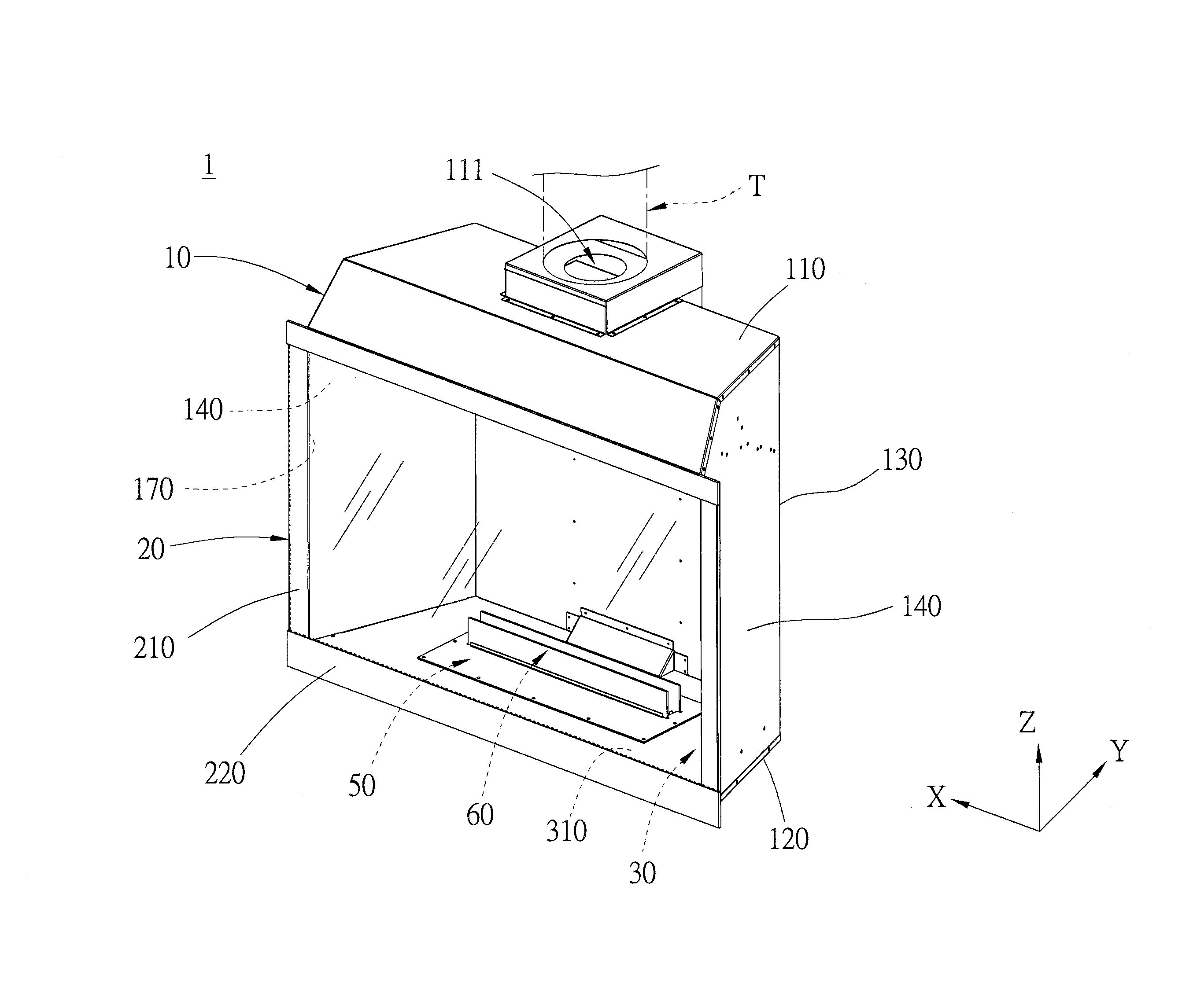
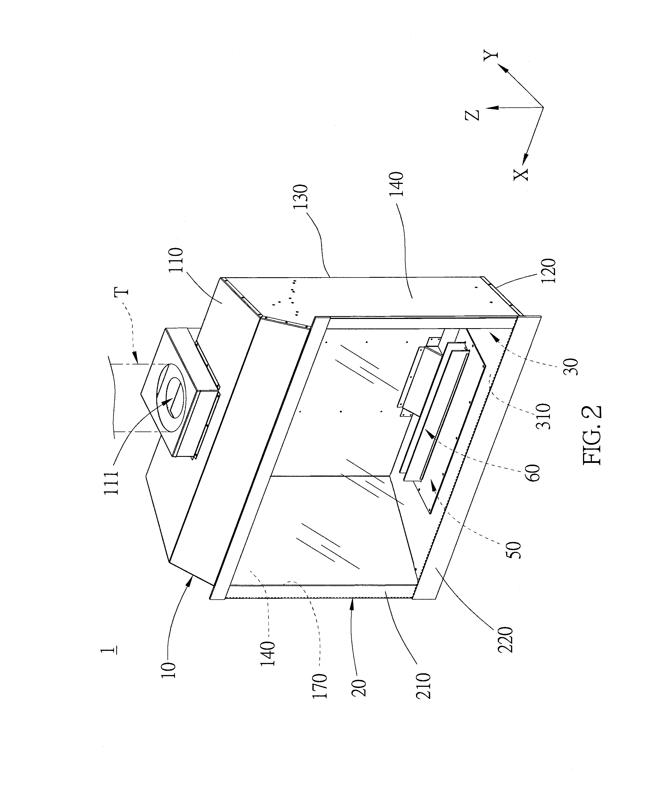
[0028]As shown in FIG. 2 to FIG. 5, a gas fireplace 1 of an embodiment of the present invention includes a firebox 10, a translucent cover 20, and a separate assembly 30. To make the following explanation more understandable, the firebox 10 is defined to have a first axial direction X, a second axial direction Y, and third axial direction Z in a three-dimensional coordinate system, wherein the first axial direction X and the second axial direction Y are different directions on a horizontal plane with an included angle formed therebetween, while the third axial direction Z points upward in a vertical direction. In the third axial direction Z, the firebox 10 has a top portion 110 and a bottom portion 120 opposite to the top portion 501, wherein an exhaust port 111a is provided on the top portion 110, and an intake port 121 is provided either on the bottom portion 120 or another location on the firebox 10 near the bottom portion 120. Forward directions of the intake port 121 and the ex...


PUM


Abstract

A gas fireplace includes a firebox, a translucent cover provided on the firebox, and a separate assembly. The separate assembly is provided in the firebox, and divides the firebox into an air chamber and a combustion chamber which corresponds to the translucent cover. An exhaust passage is formed between the separate assembly and the translucent cover, and communicates the air chamber and the combustion chamber, wherein an inner width of the exhaust passage gradually reduces from the air chamber toward the combustion chamber. During the combustion, the exhaust passage guides cold air to flow through the semi-enclosed air chamber, and to evenly blow into the translucent cover, which forms an even air curtain on a surface of a bottom portion of the translucent cover to block out the heat. Whereby, the temperature of the translucent cover and the bottom portion of the combustion chamber could be lowered.

Description

BACKGROUND OF THE INVENTION[0001]1. Technical Field[0002]The present invention relates generally to a gas-burning appliance, and more particular to a gas fireplace and a flow guide member thereof.[0003]2. Description of Related Art[0004]A conventional direct-vented gas fireplace intakes and exhausts air in a naturally balanced way, with the exhaust port and the intake port horizontally or vertically connected to the combustion chamber, and communicating with outside. The indoor air is completely isolated from the combustion chamber, which makes the direct-vented gas fireplace the safest fireplace for now. As shown in FIG. 1, a conventional direct-vented gas fireplace F includes a firebox F1 and a combustor F2, wherein a vent line F3 is provided on the firebox F1. The firebox F1 has an exhaust port F11 and an intake port F33 provided at a top thereof, wherein the exhaust port F11 and the intake port F33 both communicate with outside, and the vent line F3 is typically designed in a pi...

Claims


Application Information

Patent Timeline
Patent Type & Authority Applications(United States)
IPC IPC(8): F24B1/18F24B1/189F24B1/181
CPCF24B1/1808F23C2200/00F24B1/1895F24B1/181F24C3/006F24C3/022F24C3/082F23D14/105F23D14/72F23D2900/21004
Inventor YEH, YEN-JENLIN, KUAN-CHOUCHEN, WEI-LONG
Owner BAHUTONG ENTERPRISE LTD
Learn More