Eureka AIR delivers breakthrough ideas for toughest innovation challenges, trusted by R&D personnel around the world.

Autonomous vehicle speed calibration

a technology for autonomous vehicles and speed calibration, applied in the direction of position fixation, navigation instruments, external condition input parameters, etc., can solve the problems of fact limit or even adversely affect autonomous navigation, sheer volume of data needed to store and update the map poses daunting challenges, and may include debris

Active Publication Date: 2017-01-12
MOBILEYE VISION TECH LTD
View PDF2 Cites 370 Cited by
  • Summary
  • Abstract
  • Description
  • Claims
  • Application Information

AI Technical Summary

Benefits of technology

The patent text describes a system and method for autonomous vehicle navigation using a sparse map. The map is designed to provide enough information for navigation without requiring excessive data storage. The system analyzes images of the surrounding environment to identify important features like tire tracks, changes in light, trees, and road edges. This analysis is used to guide the vehicle's navigation between these identified edges. The technical effects of the patent text include improved efficiency and accuracy in autonomous vehicle navigation through snowy surfaces.

Problems solved by technology

Harnessing and interpreting vast volumes of information collected by an autonomous vehicle as it travels to its destination poses a multitude of design challenges.
The sheer quantity of data (e.g., captured image data, map data, GPS data, sensor data, etc.) that an autonomous vehicle may need to analyze, access, and / or store poses challenges that can in fact limit or even adversely affect autonomous navigation.
Furthermore, if an autonomous vehicle relies on traditional mapping technology to navigate, the sheer volume of data needed to store and update the map poses daunting challenges.
The obstacle may include debris.
Selectively receiving the road environment information may include a limitation on a frequency of information transmissions received from a particular vehicle.
Selectively receiving the road environment information may include a limitation on a frequency of information transmissions received from a group of vehicles.
Selectively receiving the road environment information may include a limitation on a frequency of information transmissions received from vehicles traveling within a particular geographic region.
Selectively receiving the road environment information may include a limitation on a frequency of information transmissions received from vehicles based on a determined model confidence level associated with a particular geographic region.
Selectively receiving the road environment information may include a limitation on information transmissions received from vehicles to only those transmissions that include a potential discrepancy with respect to at least one aspect of the predetermined road model.
Selectively receiving the road environment information may include a limitation on a frequency of information transmissions received from a particular vehicle.
Selectively receiving the road environment information may include a limitation on a frequency of information transmissions received from a group of vehicles.
Selectively receiving the road environment information may include a limitation on a frequency of information transmissions received from vehicles traveling within a particular geographic region.
Selectively receiving the road environment information may include a limitation on information transmissions received from vehicles to only those transmissions that include a potential discrepancy with respect to at least one aspect of the predetermined road model.

Method used

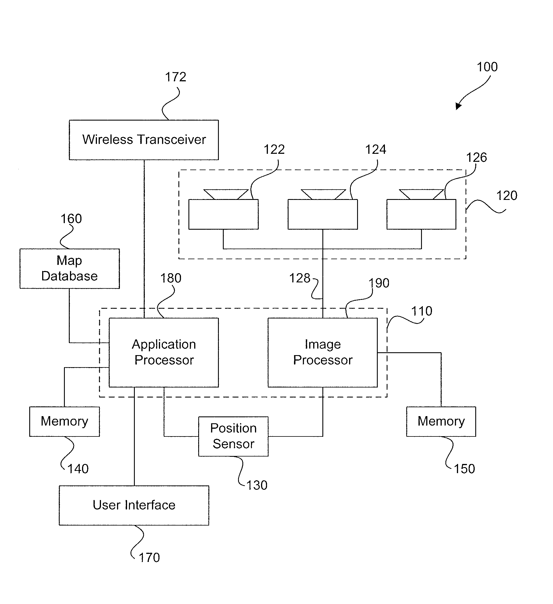
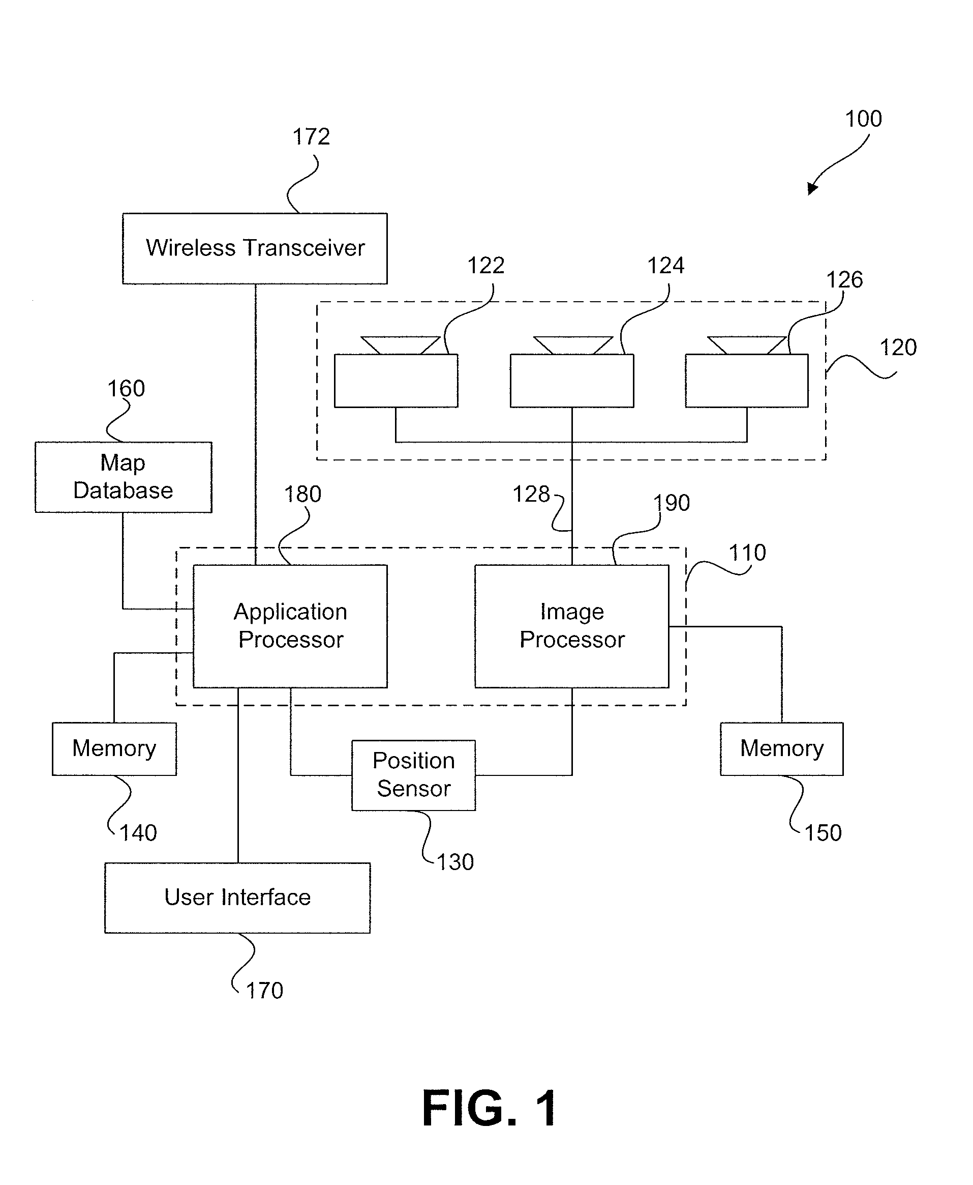
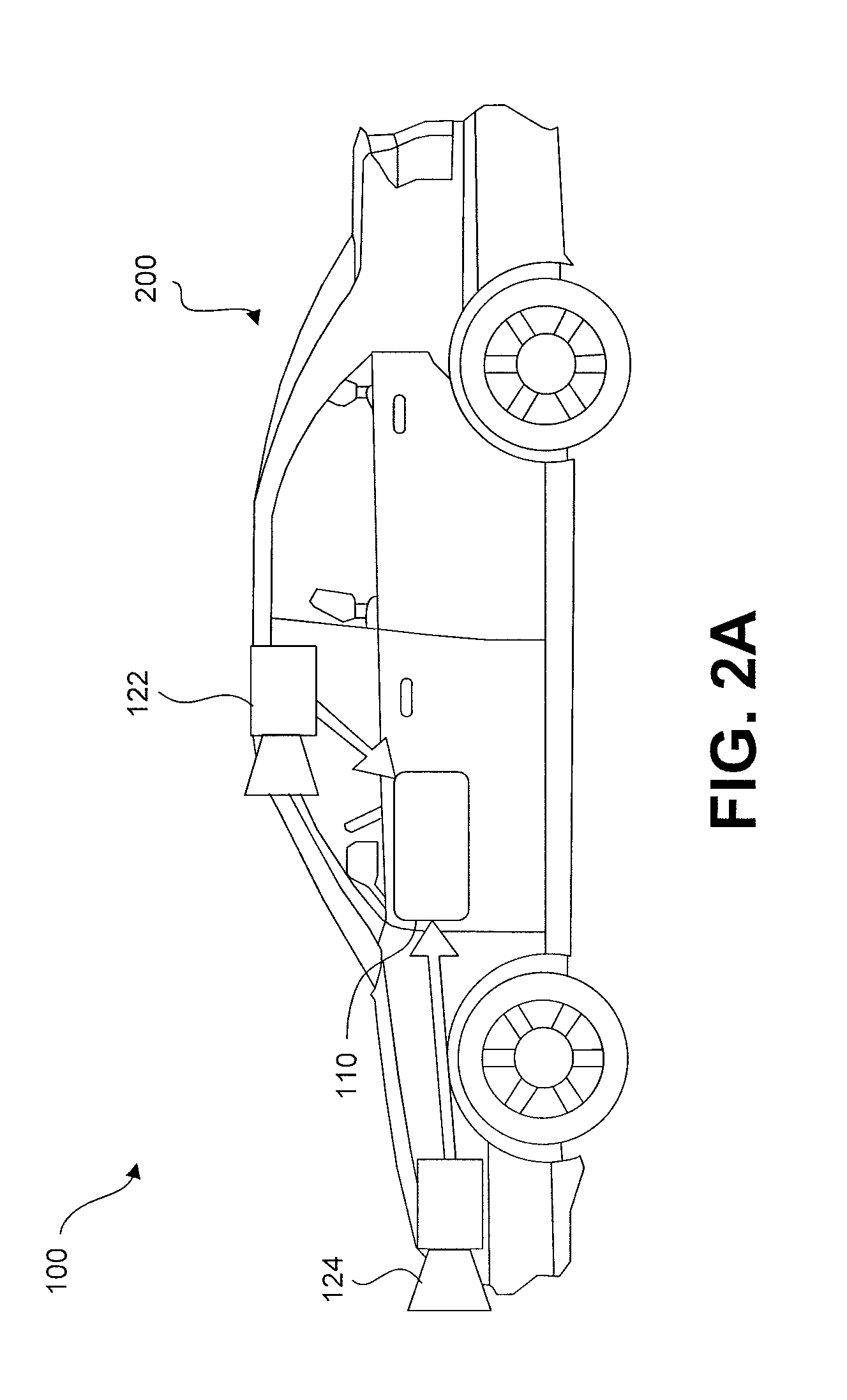

Image

  • Autonomous vehicle speed calibration
  • Autonomous vehicle speed calibration
  • Autonomous vehicle speed calibration

Examples


Embodiment Construction

[0257]The following detailed description refers to the accompanying drawings. Wherever possible, the same reference numbers are used in the drawings and the following description to refer to the same or similar parts. While several illustrative embodiments are described herein, modifications, adaptations and other implementations are possible. For example, substitutions, additions or modifications may be made to the components illustrated in the drawings, and the illustrative methods described herein may be modified by substituting, reordering, removing, or adding steps to the disclosed methods. Accordingly, the following detailed description is not limited to the disclosed embodiments and examples. Instead, the proper scope is defined by the appended claims.

[0258]Autonomous Vehicle Overview

[0259]As used throughout this disclosure, the term “autonomous vehicle” refers to a vehicle capable of implementing at least one navigational change without driver input. A “navigational change” ...


PUM


Abstract

Systems and methods may calibrate an indicator of speed of an autonomous vehicle. In one implementation, a system may include at least one processor programmed to: receive from a camera at least a plurality of images representative of an environment of the vehicle; analyze the plurality of images to identify at least two recognized landmarks; determine, based on known locations of the two recognized landmarks, a value indicative of a distance between the at least two recognized landmarks; determine, based on an output of at least one sensor associated with the autonomous vehicle, a measured distance between the at least two landmarks; determine a correction factor for the at least one sensor based on a comparison of the value indicative of the distance between the at least to recognized landmarks and the measured distance between the at least two landmarks.

Description

CROSS REFERENCES TO RELATED APPLICATIONS[0001]This application claims the benefit of priority of U.S. Provisional Patent Application No. 62 / 114,091, filed on Feb. 10, 2015; U.S. Provisional Patent Application No. 62 / 164,055, filed on May 20, 2015; U.S. Provisional Patent Application No. 62 / 170,728, filed on Jun. 4, 2015; U.S. Provisional Patent Application No. 62 / 181,784, filed on Jun. 19, 2015; U.S. Provisional Patent Application No. 62 / 192,576, filed on Jul. 15, 2015; U.S. Provisional Patent Application No. 62 / 215,764, filed on Sep. 9, 2015; U.S. Provisional Patent Application No. 62 / 219,733, filed on Sep. 17, 2015; U.S. Provisional Patent Application No. 62 / 261,578, filed on Dec. 1, 2015; U.S. Provisional Patent Application No. 62 / 261,598, filed on Dec. 1, 2015; U.S. Provisional Patent Application No. 62 / 267,643, filed on Dec. 15, 2015; U.S. Provisional Patent Application No. 62 / 269,818, filed on Dec. 18, 2015; U.S. Provisional Patent Application No. 62 / 270,408, filed on Dec. 21,...

Claims


Application Information

Patent Timeline
Patent Type & Authority Applications(United States)
IPC IPC(8): B60W30/18G08G1/0967G01C21/32G01C21/14G05D1/00G05D1/02
CPCB60W30/18G05D1/0088G05D1/0278G01C21/32B60W2720/10G08G1/096725B60W2420/42B60W2550/22G01C21/14G01C21/1656G01C21/1652G01C21/3896G01C21/3819G01C21/3822G01C21/3811G06F16/29B60W40/06B60W30/10B60W60/0015B60W2554/40B60W2554/60B60W2554/20G01C21/3658G01C21/20G01S13/867G01S2013/93271G06V20/56G06V20/582G06V20/63B60W60/00B60W2552/30B60W2556/40B60W2556/45B60W2556/50B62D15/025G01C21/3602G01C21/3644G01C21/3841G01S5/0027G01S5/16G06V20/58G06V20/588G06V20/64G08G1/0112G08G1/0129G08G1/0141G08G1/0145G08G1/09623G08G1/096805H04W4/44G01C21/30B60W2420/403G01C21/3407G01C21/3446G01C21/3476G01C21/3623G01C21/3691G01S19/10B60W30/14G06F16/2379G08G1/167G06T7/00H04L67/12B60W2555/60B60W2710/18B60W2710/20G01C21/165G05D1/0221G05D1/0212G05D1/0246G05D1/0287G05D1/0251G05D1/0253G05D1/0219G06V20/584B60W2552/53B60W2556/35B60W60/00274B60W2420/408G01C21/34G01C21/36G06T2207/20081G06T2207/30256G06T2207/30261
Inventor BRAUNSTEIN, DANIELGDALYAHU, YORAMRUBINSKY, SERGEY
Owner MOBILEYE VISION TECH LTD
Why Eureka
Eureka Blog
Learn More